7
4
3.3) Electrical connections
!
To safeguard the operator and avoid damaging the components, make sure that the control unit is switched off while you
are wiring or plugging in the various cards.
•Powerthecontrolunitusinga3x1.5mm
2
cable; should the distance between the unit and the earth connection exceed 30m, install an
earth plate near the unit.
•Usewireswithaminimumcross-sectionof0.25mm
2
to connect extra-low voltage safety circuits.
•Useshieldedwiresifthelengthexceeds30mandonlyconnecttheearthbraidtothecontrolunitside.
•Donotmakeconnectionstocablesinburiedboxeseveniftheyarecompletelywatertight.
•IftheinputsoftheNormallyClosed(NC)contactsarenotused,theyshouldbejumpedwiththe“24Vcommon”terminalexceptforthe
photocellinputsifthephototestfunctionisenabled.Forfurtherinformationpleaseseetheparagraph3.5“Notesaboutconnections“inthe
part“Phototest“.
•Ifthereismorethanone(NC)contactonthesameinput,theymustbeconnectedinSERIES.
•IftheinputsoftheNormallyOpen(NA)contactsarenotusedtheyshouldbeleftfree.
•Ifthereismorethanone(NA)contactonthesameinput,theymustbeconnectedinPARALLEL.
•Thecontactsmustbemechanicalandpotential-free;nostageconnectionsareallowed,suchasthosedenedas“PNP”,“NPN”,“Open
Collector”,etc.
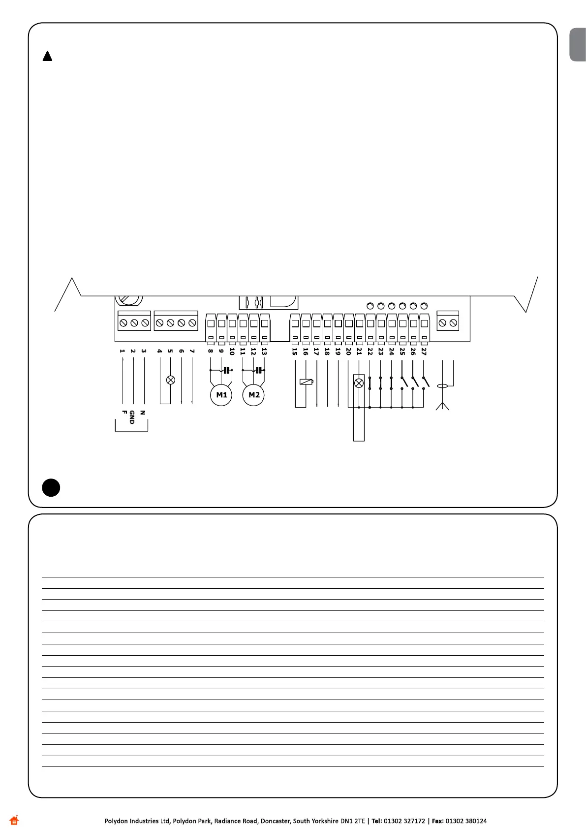
Carry out the necessary connections, following the diagram in Fig. 4 and the following description of the connections.
Rememberthattherearespecicstandardsthatmustbecompliedwithbothasregardsthesafetyoftheelectricalsystemsandasregards
automatic gates.
3.4) Description of electrical connections
The following table provides a brief description of the possible control unit output connections.
Terminals Function Description
1-2-3 : Power supply = Mains power line
4-5: Flashinglight= Outputforconnectingashinglighttomainsvoltage(Max.40W)
6-7: Courtesylight= Cleancontactoutputforcourtesylightconnection(Max.5A)
8-9-10 : Motor1 = Motor 1 control output,
11-12-13 : Motor2 = Motor 2 control output
15-16 : Electric lock = 12 Vdc output for electric lock activation, max. power 25W
17-18: 24Vac= Powersupplyto24Vacservices(Max.200mA)
19: Phototest= Phototestoutput-“TX”powersupplytophotocells-(Max.75mA)
20 : Common = Common for all inputs
21: AClight= 24Vacoutputforopengateindicatorlight(Max.2W)
22: Stop= Inputwith“Stop”function(Stopandshortreverserun)
23 : Photo = Input for safety devices
24 : Photo1 = Input for additional safety device
25: Stepbystep(PP)= Inputforcyclicmovement(“Open”–“Stop”–“Close”–“Stop”)
26 : Open = Input for opening function
27 : Close = Input for closing function
Aerial = Input for the radio receiver aerial
Close
Motor 2 Close
Motor 2 Common
Motor 2 Open
Motor 1 Close
Motor 1 Common
Motor 1 Open
Open
Step by step
Photo1
Photo
Stop
AC light
Common
Phototest
24 Vac ~
200mA
Electric lock
12Vdc Max 25W
Courtesy light
Power supply
Flashing light
Max 40W
EN

 Loading...


