5
2.1) Operating limits
Chapter9“TechnicalCharacteristics”providestheonlydataneededtodeterminewhethertheproductsaresuitablefortheintendedappli-
cation.
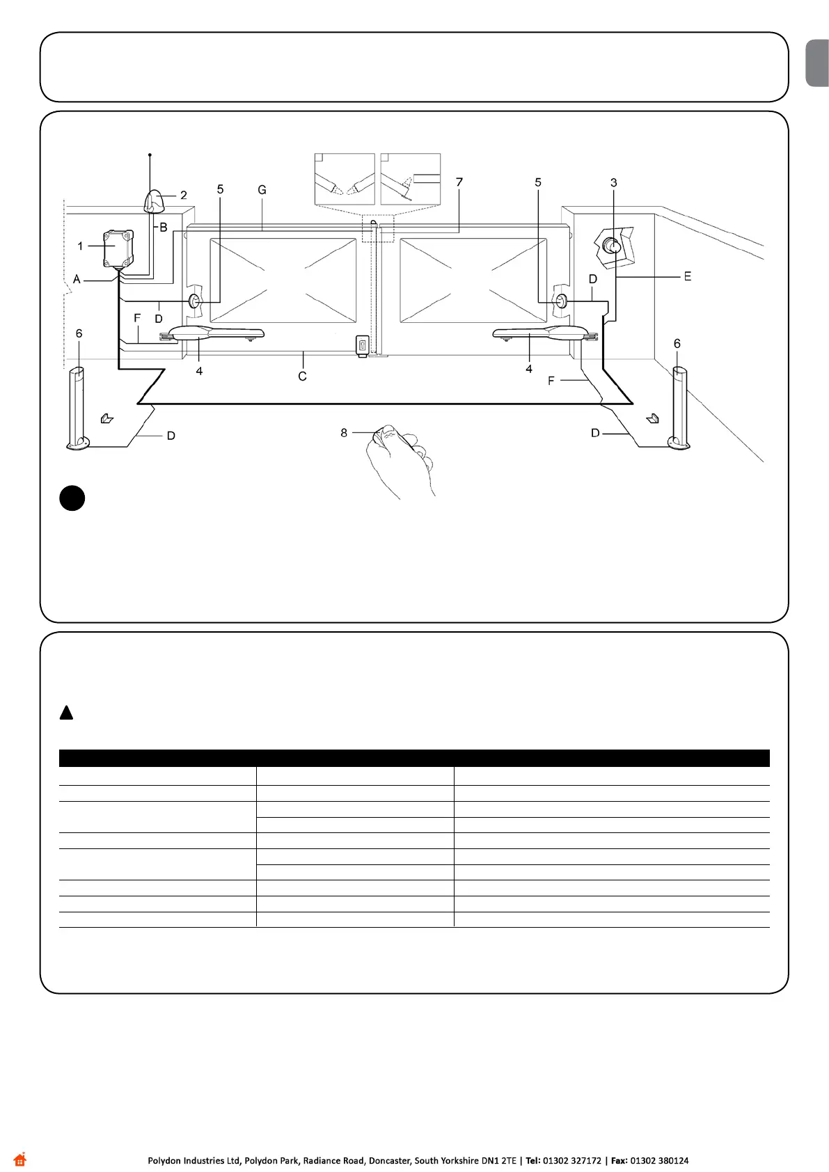
2.2) Typical system
1. Control Unit A60
2. Flashing light with incorporated aerial
3. Key-operatedselectorswitch
4. Motors
5. Couple of photoelectric cells PHOTO
6. Couple of photoelectric cells PHOTO 1
7. Sensitive edge
8. Radio transmitter
2
2.3) List of cables
Thetypicalsystemshowningure2alsostatesthecablesrequiredforconnectionofthevariousdevices,thespecicationsofwhichare
provided in table 1.
!
The cables used must be suitable for the type of installation; for example, an H03VV-F type cable is recommended for indoor
applications, while H07RN-F is suitable for outdoor applications.
Note 1: power supply cable longer than 30m may be used provided it has a larger gauge, e.g. 3x2,5mm
2
, and that a safety earthing system
is provided near the automation unit.
Connection Tipo cavo Maximum admissible length
A: Electrical power line N°1 cable 3x1,5mm
2
30m(note1)
B: Flashing light with aerial N°1 cable 2x0,5mm
2
20m
N°1shieldedcabletypeRG58 20m(lessthan5mrecommended)
C: Electric lock N°1 cable 2x1mm
2
20m
D: Photocells N°1 cable 2x0,25mm
2
(Tx) 30m
N°1 cable 4x0,25mm
2
(Rx) 30m
E: Key-operatedselectorswitch N°1cable4x0,25mm
2
30m
F: Connection to the motors. N°1 cable 4x1,5mm
2
3m
G: Connection to sensitive edge N°1 cable 2x0,25mm
2
30m
Table 1: List of cables
EN

 Loading...


