Chapter 7 Assembly of the Devices
142
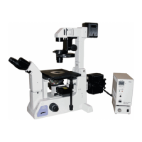
7.7.4 Restriction on Stage Strokes (Manual Stage Only)
The maximum movable range (stroke) of the manual stage is 114 mm (X direction) x 73 mm (Y direction) and
this can be restricted.
Two types of the stroke limit screws are supplied with the manual stage.
1. Attach the stroke limit screw (knurled
screw) at the restricting position of the X
stroke on the reverse surface of the stage.
ttaching the knurled screw at stroke restricting
position 1 restricts the movable range in the X
direction to 75 mm.
ttaching the knurled screw at stroke restricting
position 2 restricts the movable range in the X
direction to 18 mm.
Attaching the X stroke limit screw
In the case of stroke restriction in the
X-direction, the stroke limit screw can be
attached before mounting the stage on the
microscope main body.
Restricting the X stroke
2. Move the stage up to the position where the
screw hole for Y-stroke restriction can be
seen.
3. Attach the stroke limit screw (hex socket
head cap screws) at the Y-stroke restricting
position on the front surface of the stage
using a hexagonal screwdriver.
(Tool: 2 mm hexagonal screwdriver, supplied with
the microscope main body)
Attaching the knurled screw at stroke restricting
position 1 restricts the movable range in the Y
direction to 50 mm.
ttaching the knurled screw at stroke restricting
position 2 restricts the movable range in the Y
direction to 18 mm.
Restricting the Y stroke
Stroke restricting position 2
Stroke restricting position 1
Reverse surface
of the stage
Front surface of
the stage
Stroke restricting position 1
Stroke restricting position 2
X direction
direction
X direction
direction
 Loading...