Chapter 3 Usage of Components
49
NAMC condenser slit image and slit diaphragm adjustment
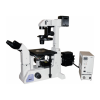
In the NAMC condenser module, there are two
apertures (slit diaphragms) indicated by (1) and (2) in
the right figure, and a space called “bridge” indicated
by (3) between the apertures.
A polarizing plate is in aperture (2) and the
brightness of (2) is changed by changing the azimuth
of the polarizer.
Slit adjustment
Observe the slit image using the centering telescope.
djust the orientation of the slit diaphragm by turning
the NAMC condenser module so that apertures (1)
and (2) are parallel to gray zone (G) of the
modulator.
Adjust the position of the slit to cause the portion of
the slit aperture image (1), which does not change its
brightness by moving the polarizer, to overlap with
the gray zone (G).
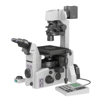
Operation:
Module adjustment Polarizing plate
Turn the centering screw.
The position of the slit
diaphragm is changed.
Turn the module through
the module rotation slot.
The orientation of the slit
diaphragm is changed.
Slit diaphragm image
Slit diaphragm adjustment
Fine adjustment of the NAMC condenser slit diaphragms
Images obtained by NAMC microscopy vary depending on the slit diaphragm adjustment of the NAMC
condenser module.
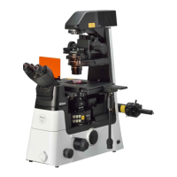
Emphasizing on 3D effects:
Align the inner side plane (A) of the objective's gray
zone (G) with the inner plane of aperture (1).
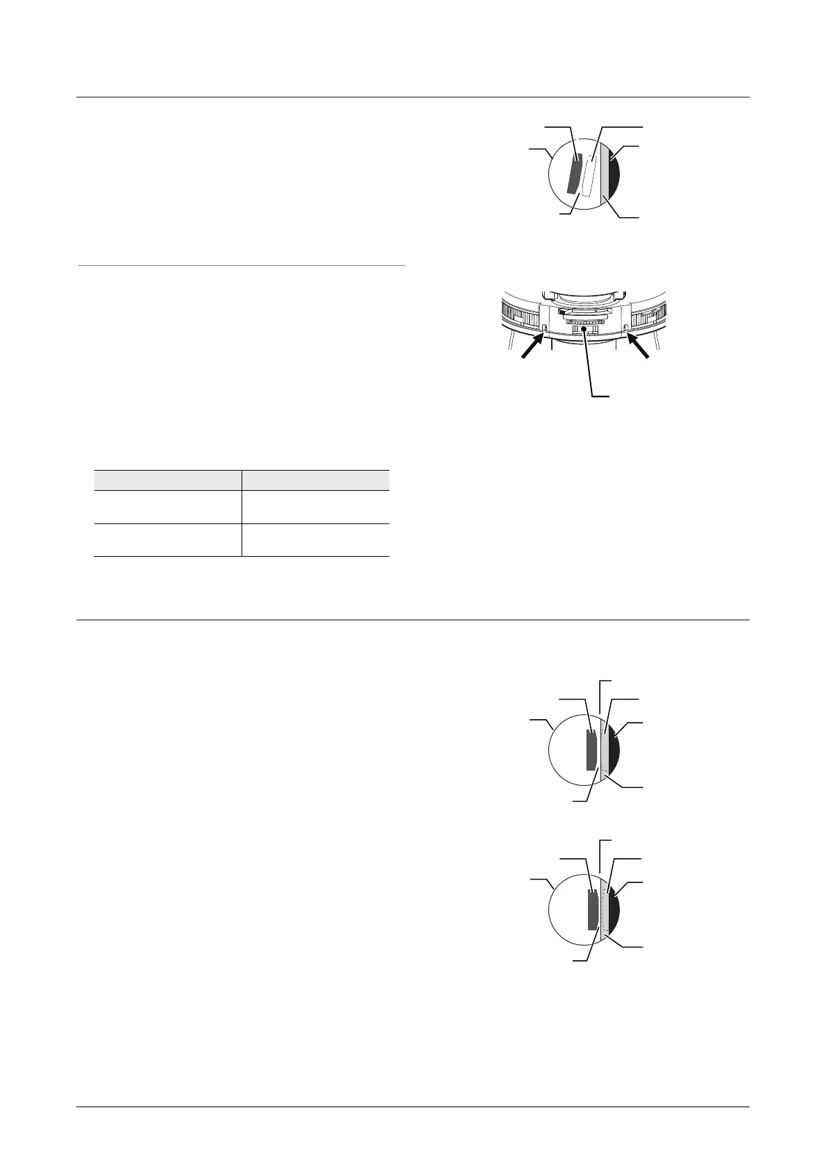
Reducing the contrast degradation due to
leakage light:
lign the inner side plane (A) of the objective's gray zone (G)
with the center of the bridge section (3).
(2)
Dark region (D)
(3) Bridge section
(1)
Objective pupil
Gray region (G)
(A)
Dark region (D)
(2)
(3) Bridge section
(1)
Objective pupil
Gray region (G)
(A)
Dark region (D)
(2)
(3) Bridge section
(1)
Objective pupil
Gray region (G)
Module rotation slot
Centering screw Centering screw
 Loading...