Description
2-2
Part 1128350_02
E 2020 Nordson Corporation
Key Components
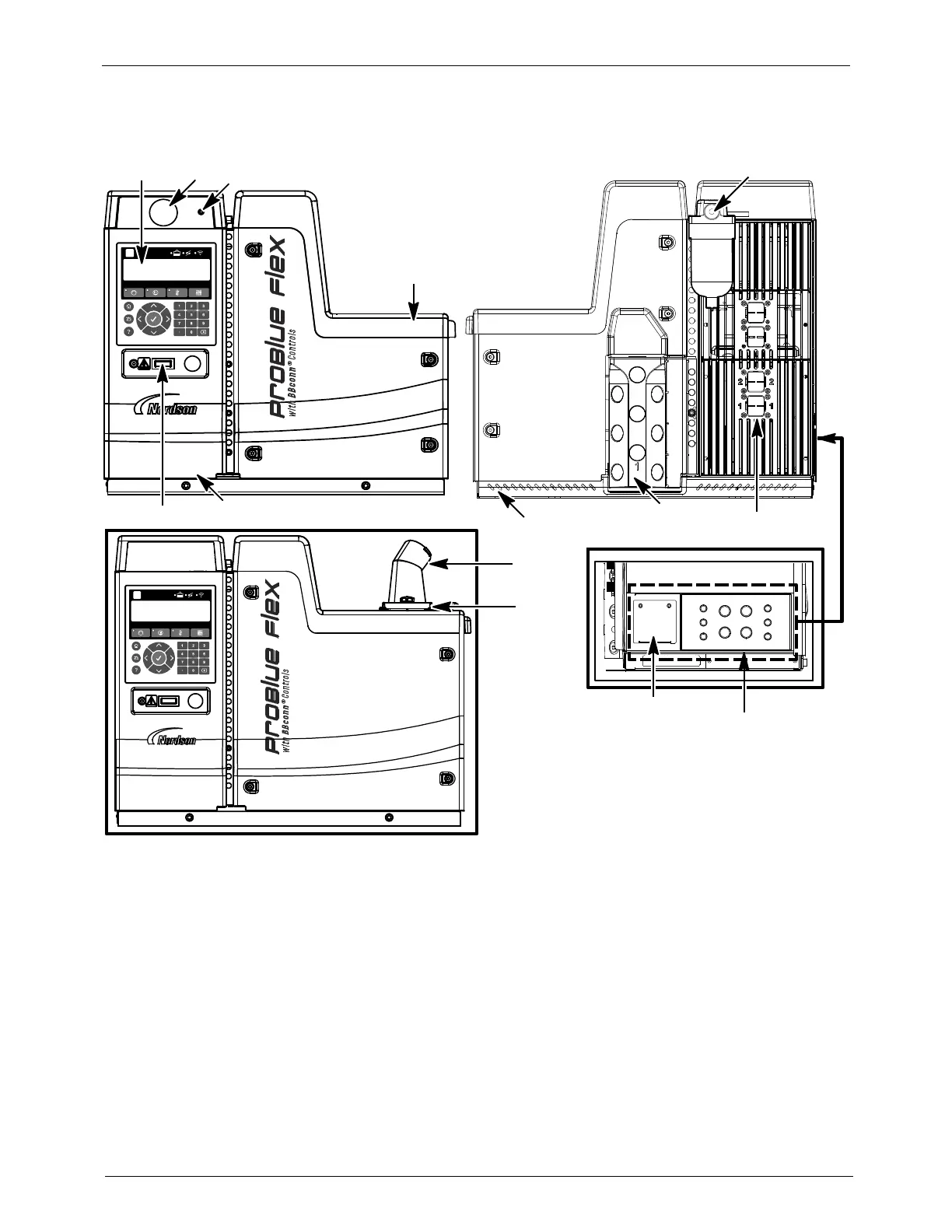
Figures 2-2 and 2-3 display the name and the location of key melter components.
2
6
4
1
10
3
9
11
12
13
14
5
7
8
Figure 2-2 Key melter components
1. OLED user interface
2. Air pressure gauge (optional)
3. Air pressure adjustment screw
4. Lid assembly
5. Melter On/Off switch
6. Electrical enclosure door
7. Chassis
8. Incoming air filter
9. Customer I/O knockout panel
10. Incoming AC power plate
11. Hose and applicator 12-pin
connectors
12. Hose manifold assembly
13. Adhesive transfer hos e
connection (optional with Fill
system)
14. Fill system air filter (optional
with Fill System)

 Loading...