Installation
3-36
Part 1128350_02
E 2020 Nordson Corporation
Set Up the Melter Inputs and Outputs (I/O)
To access the electrical boards in the E-Box enclosure, make sure that the
E-Box enclosure door is open and the enclosure side panel is removed.
Refer to step 2 in Removing the Melter from the Sub-base givenearlierinthis
section.
I/O Connections
Refer to Technical Data (Section 7) given later in this manual for specific
board details.
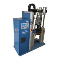
INPUT: 10-30VDC
OUTPUT: 2A@ 30VDC or
250VAC
FILL OUTPUT: 24VDC
DETECT: ACTIVE
LOW
A13 PRESSURE
INPUT
A14 PRESSURE CONTROL
A3 Low Voltage Control Boar d
Figure 3-17 Low v oltage controller board I/O connections
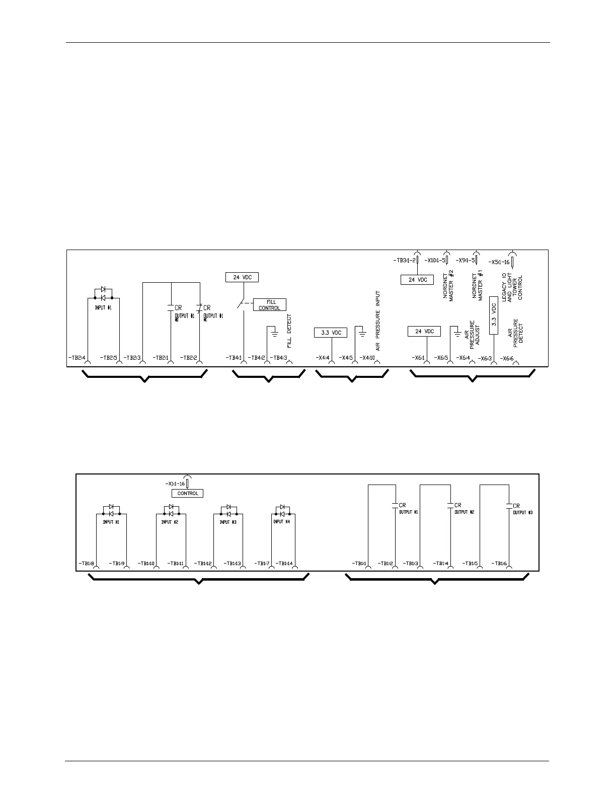
OUTPUT: 2A@ 30VDC or 250VAC
A4 Legacy I/O Board
INPUT: 10-30VDC
Figure 3-18 Legacy board I/O connections

 Loading...