Installation
3-10
Part 1128350_02
E 2020 Nordson Corporation
Customer-Supplied Materials
The following additional materials are also require d to install t he melter:
S Power cable (if the cable clamp provided in the installation kit is not
used, a rigid or flexible electrical conduit will be required.)
S Four 8 mm (
5
/
16
in.) machine bolts with locking hardware
S A plant air supply with an in-line isolation valve
Mount the Melter
ProBlue Flex adhesive melters come factory-installed with the sub-base. At
thetimeofmounting,thesub-baseneedstoberemovedfromthemelterand
mounted onto the parent machine or support structure. The melter is then
remounted onto the sub-base.
1
2
3
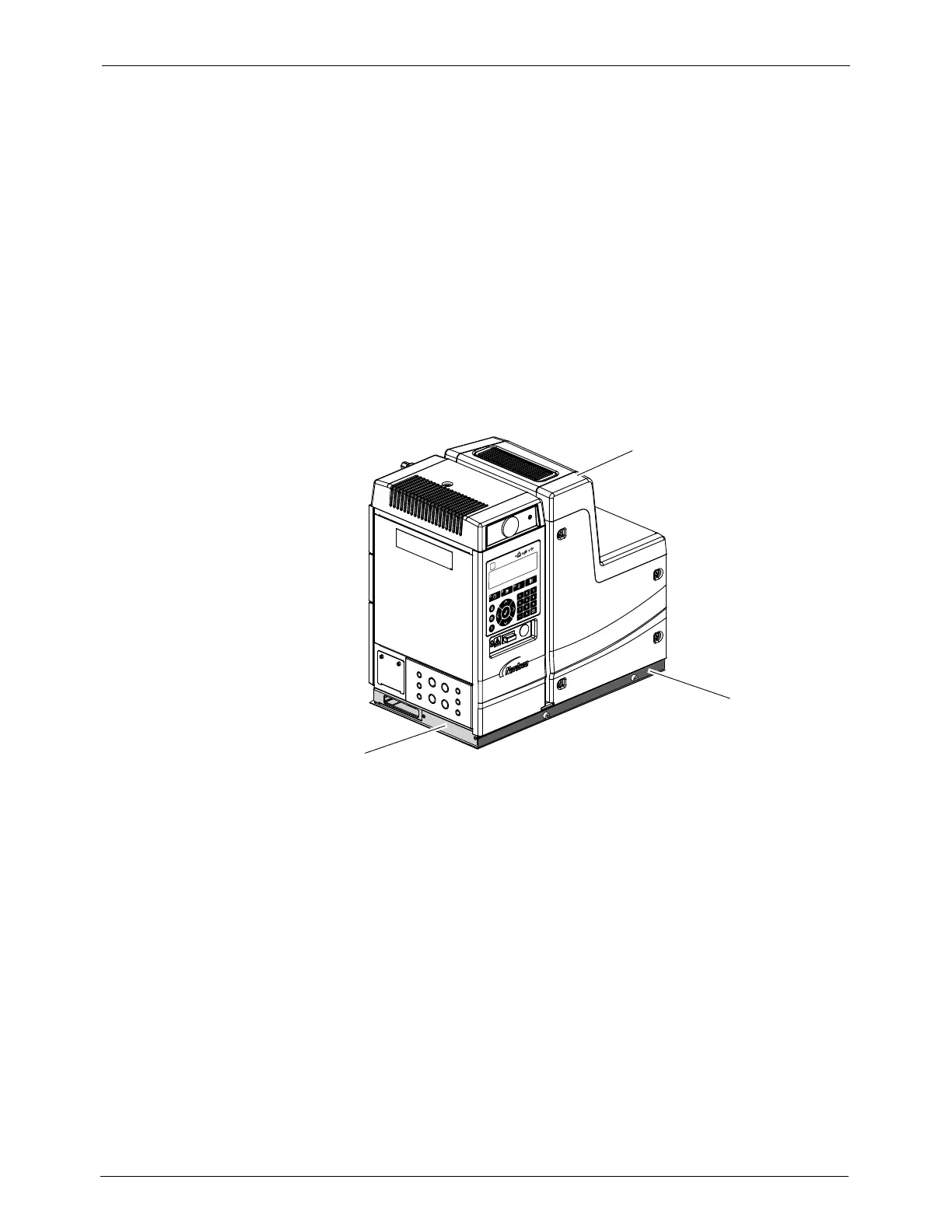
Figure 3-5 Melter with the chassis and sub-base
1. ProBlue Flex melter
2. Sub-base
3. Chassis
Refer to Technical Data (Section 7) for the dimensions of the melter and the
sub-base. Refer to the technical data provided by the hot melt manufacturer
for information about the volumet ric weight of the hot melt.

 Loading...