Installation
3-21
Part 1128350_02
E 2020 Nordson Corporation
Connecting Power Cables
SeeFigure3-11.
To configure the melter to function in your facility, you must connect a power
cableandaNordsonvoltageplugtothemelter.
1. Select a power cable rated for the maximum amperage required by the
melter. Ensure that the power cable meets applicable electrical codes
and standards.
The maximum power draw for each melter shipping configuration,
operating at 240 volts, in both 1-phase and 3-phase is listed in
Table 3-3. The values presented in the table assume that each
hose/applicator module is being used at i ts maximum capacity of
2000 watts.
NOTE: Contact your Nordson representative for assistance in calculating
the melter's power draw for o perating voltages other than 230 volts or for
assistance in calculating the exact power draw for specific hoses and
applicators that are manufactured by Nordson Corporation. Also refer to
Calculating Melter Power Requirements (Appendix A).
WARNING! Risk of electrocution! Install a lockable power disconnect switch
between the electrical service and the melter. Failure to install or properly
use the disconnect switch when servicing the melter can result in personal
injury, including death.
2. Access the electrical boards in the E-Box enclosure. To open the E-Box
enclosure door and remove the enclosure side panel, refer to step 2 in
Removing the Melter from the Sub-base givenearlierinthissection.
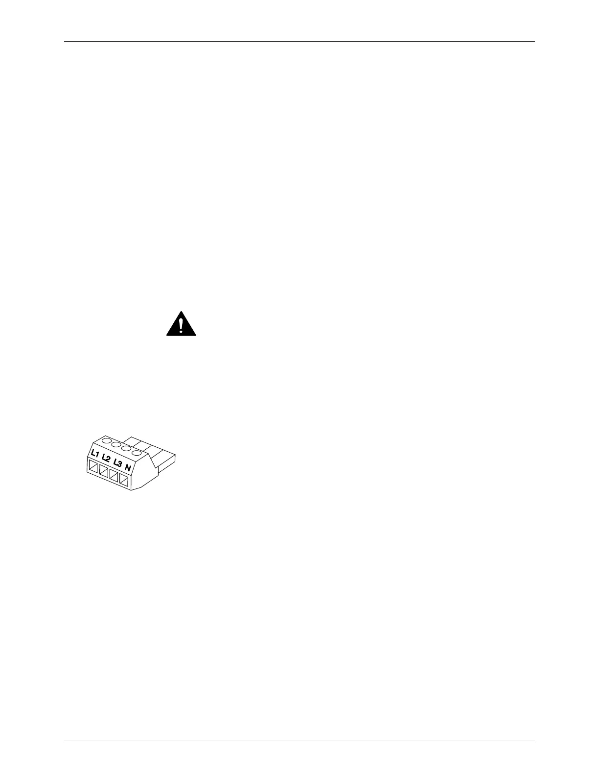
3. Connect each power cable lead to the appropriate terminal on the
electrical connector (P/N 1022993). See figure on the left.

 Loading...