ProBlue Flex 400/480 Volt Transformer
F-19
Part 1128350_02
E 2020 Nordson Corporation
1
2
3
4
J7
J3
X9
X10
J2
XT1
J5
J6
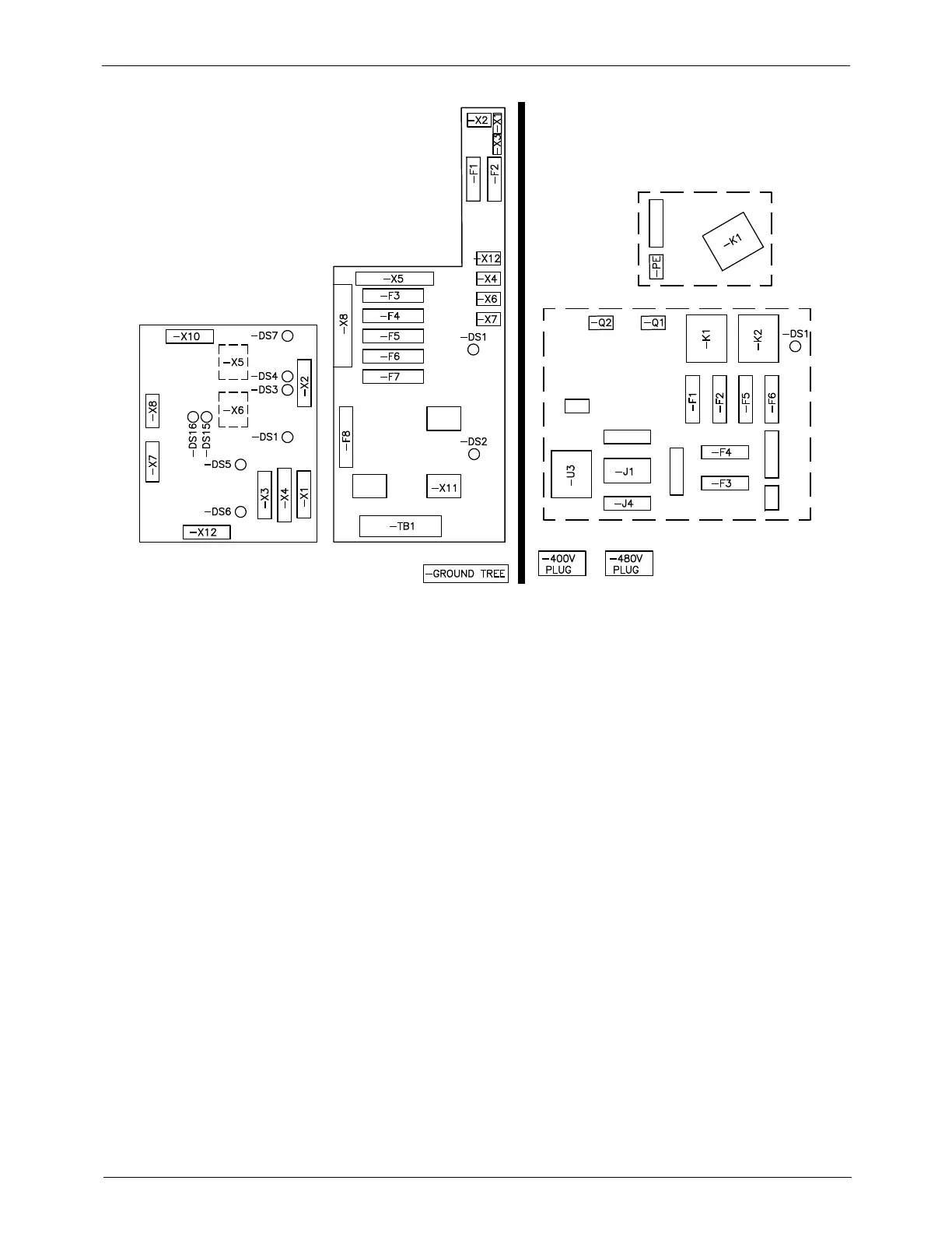
Figure F-14 Connecting the electrical service in the E-Box
1. Transformer PCA tray electrical layout
2. Transformer base
3. Melter E-box power distribution
board
4. Melter E-box 6-Channel
power board
6. After the electrical service is completely installed and inspected in
accordance with local electrical codes and standards:
a. Remove the two side spacers positioned between the melter and
transformer.
b. Close the melter's E-Box door and reinstall the side enclosure panel.
7. Switchonthelocalpowerdisconnectswitch.

 Loading...