43984801TH Rev.1
54 /
Oki Data CONFIDENTIAL
3. Parts replacement
3.3.16 Frame-Assy-Lower
(1) Open Rear-Cover-Assy.
(2) Open Stacker-Cover-Assy.
(3) Remove Cover-Side-R. Remove Cover-Side-L. (Refer to 3.3.3/3.3.4)
(4) Remove CU Board. (Refer to 3.3.5)
(5) Remove Motor-DC-Main. (Refer to 3.3.6)
(6) Remove Piece-Guide
.
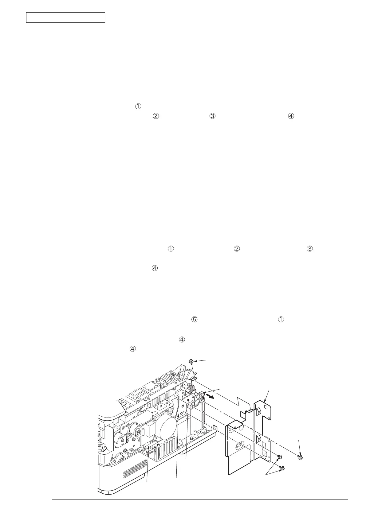
(7) Remove the 3 screw (Silver)
and screw (Black) . Remove Plate-Shield-CU .
(8) Pass the connector of Low Voltage Power Board through the Portion A of Plate-Bracket-Motor from
above to the downward.
(9)
Remove OPE Cover-Assy. (Refer 3.3.7)
(10) Remove MPT-Assy. (Refer to 3.3.9)
(11) Remove Front-Guide-Assy. (Refer to 3.3.10)
(12) Remove Roller-Assy-Feed. (Refer to 3.3.11)
(13) Remove Guide-Paper-Duplex. (Refer to 3.3.12)
(14) Remove Stacker-Cover-Assy. (Refer to 3.3.13)
(15) Remove Fuser-Assy. (Refer to 3.3.14)
(16) Remove Rear-Cover-Assy. (Refer to 3.3.15)
(17
) Remove all the cable from Hook A of Holder-SNS, extend them and put on the right front side of the
printer.
(18) Remove connector B from high voltage power board.
(19) Remove the 4 long screws (Silver)
, the 4 screws (Black) , the short screw (Silver) .
(20) Remove Hook C and Hook D of Plate-Base-PCB using minus driver.
(21) Remove Frame-Assy-Lower
.
(22) Installing is performed by the inverse procedure with removing.
(Note on removing / installing)
1
. B
eware of not to touch the DC motor inattentively (Do not rotate motor).
2. A
bout the installing of Rear-Cover-Assy
, remove Cover-Face Up-A , make the supporting
point part to a bowed situation and then perform installing.
3. While installing Frame-Assy-Lower
, beware of not to tuck Cable
Ⓕ
and Cable
Ⓖ
between
Frame-Assy-Lower and Plate-Base-PCB.
Plate-Braket-Motor
A
②
②
③
①
④
Supporting point
 Loading...