Hunter-Pro Series
11
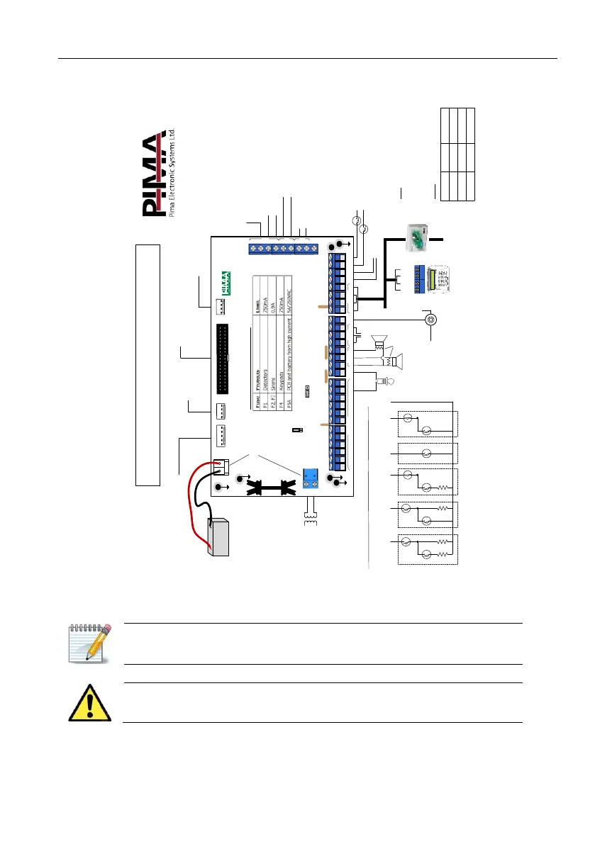
1.4. Wiring diagram
Diagram 2. Hunter-Pro Series wiring diagram
1.5. Zones and peripherals connection
The overall length of the BUS wires cannot exceed 500 meters.
If a longer distance is required, refer to section 1.5.9, on page 16.
The BUS uses PIMA proprietary protocol.
Before you begin the installation process, make sure the control
panel is not connected to battery or AC power.
1KΩ
To
(+)
Red (+)
Black (-)
Rechargeable
Lead-Acid battery
EXPANSION CARD
SERIAL
KEYPAD
TRANSMITTER
JP
1
JP
2
JP
4
F
3
F1
JP
6
F
4
F
2
JP3
HUNTER
-
PRO
P
JP
11
1
TMPR
2
TMPR
1
ON
/
OFF
ALRM
Z
1
Z
2
Z
3
Z
4
-
+
Z
7
Z
8
-
+
KEY
-
Int
C
Z O N E S
S
moke
RELAY
SIRENS
KEYPAD
Ext
N
.
O
-
-
+
IN
OUT
1
2
3
4
N
.
C
Z
5
Z
6
Current limiting thermal fuses
Warning: High voltage!
Disconnect AC power and telephone line prior to servicing
TRU-100/TRV-100 Long Distance Radio,
GSM-200 Cellular Module,
SMS-100 Module Technician
keypad
OUT-1000,
EXP-PRO UNIV
Local expanders
VVR, net4pro,
Home Automation systems
Phone line
MIC-200, VU-20U
(The two modules cannot
be used together!)
MIC-200, VU-20U,
SMS-100 GSM-200 Voice
Answering machine,
fax, telephone sets
2
Transistor outputs
22 JUL 11 22:40
--_----FB__--A-_
4 (IN)
3 (OUT)
2 (+)
1 (-)
BUS
Optional N
.
O
.
or N
.
C
.
serial
&
parallel EOL resistors loops
JP11: EOL resistor loops
TMPR1/2
TMPR2 can serve
as a zone input
(-)
Relay
To zone
input
Fire/Smoke
Detector
Z
1
Z
2
Z
3
Z
4
Z
5
(
-
)
N
.
O
./
N
.
C
.
,
2
EOL
Resistors
N
.
O
.
,
1
EOL
Resistor
N
.
C
.
,
1
EOL
Resistors
N
.
O
.
N
.
C
.
Key
Sirens
To Expanders
& Keypads
A
A
A
A
A
T
T
T
T
T
:
Tamper A
:
Alarm
Hunter-Pro Series (Ver. P )
R
2
R
1
R
1
R
1
AC
14
VAC
BATT
CONT
IN
OUT
LINE
SET
AUDIO
AGND
P/N 31610100 REV. E.
EGND
JP6: Sirens power source
- Battery: short pins 1-2
- Unregulated (AC): short pins 2-3
Detachable
1
1-2
2-3
No Pin
10
Short PinsR2 (KΩ)
10
13
5.1
10
6.8
R1 (KΩ)
 Loading...