Hunter-Pro Series Captain 8 - Installation Guide
12
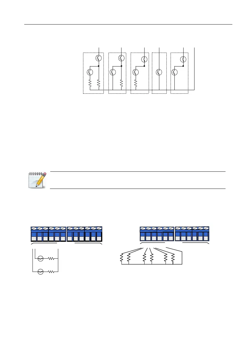
1.5.1. Zone wiring
Diagram 3. Zone wiring options diagram
1.5.2. EOL loops wiring
To set a zone loop with one or two EOL resistors, refer to parameter “E” in the “Zone
characteristics” screen, (see page 47) and “Key #5: General Parameters”, first screen,
parameter "2" (see page 62).
1.5.3. Zone doubling
Expand the onboard zones (8) with eight additional zones, without using any expansion card.
Use 10k and 5.1k resistors for each zone couple.
Zone doubling is enabled only when no expander is connected to the system.
To use zone doubling follow the next steps and diagram:
1. Connect zones #1 and #9 to terminal Z1.
2. Connect zones #2 and #10 to terminal Z2.
3. Connect zones #8 and #16 to terminal Z8.
Diagram 4. Zone doubling wiring diagram
Z
1
Z
2
Z
3
Z
4
Z
5
(
-
)
N
.
O
./
N
.
C
.
,
2
EOL
Resistors
N
.
O
.
,
1
EOL
Resistor
N
.
C
.
,
1
EOL
Resistors
N
.
O
.
N
.
C
.
A
A
A
A
A
T
T
T
T
T
:
Tamper
A
:
Alarm
R
2
R
1
R
1
R
1
Zone 1
Zone 9
R1
R2
Z
1
Z
2
Z
3
Z
4
Z
7
Z
8
-
+
Z O N E S
-
+
Z
5
Z
6
R1: 10KΩ 1/4 w
R2: 5.1KΩ 1/4 w
Z
1
Z
2
Z
3
Z
4
Z
7
Z
8
-
+
Z O N E S
-
+
Z
5
Z
6
R1
Z1 Z9
R1
Z2 Z10
R1
Z3 Z11
R2 R2 R2
 Loading...