3.3 Design
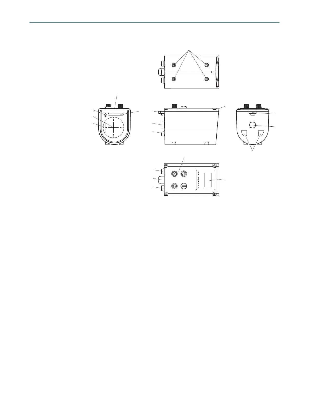
Figure 2: Dx1000 design
1
Mounting thread M5 x 6
2
Distance measurement zero point
3
Mounting points for the alignment bracket (accessory)
4
Pressure compensation element
5
Touch display
6
Electrical connection:
1 Power/RS-422/SSI
2 Auxilliary
3 not assigned, do not remove (glued) protection cap!
4 Ethernet
7
Status indicator
8
Measurement laser optical axis
9
Receiver optical axis
ß
Alignment laser optical axis
3.4 Product ID
Type label
The following information can be read off the device from the type label:
PRODUCT DESCRIPTION 3
8019329/12TZ/2019-03-28 | SICK O P E R A T I N G I N S T R U C T I O N S | DT1000 and DL1000
15
Subject to change without notice

 Loading...


