1
2
3
4
PWR
In1
/
Q1
QA/Q2
Q3
Q4
In2
LNK
BUS
3
4
1
2
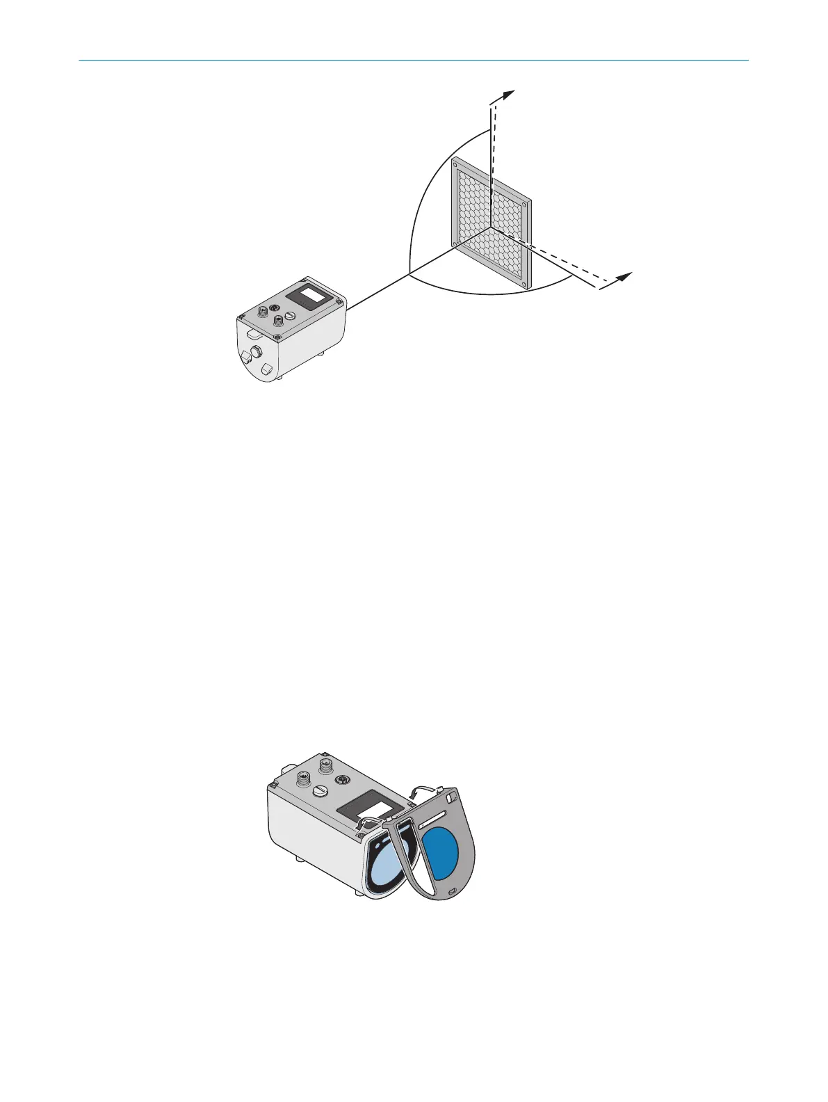
Figure 9: Reflector tilt
1
Distance sensor
2
Tilt of the vertical axis of the reflector approx. +1°…+3°
3
Reflektor
4
Tilt of the horizontal axis of the reflector approx. +1°…+3°
Avoid shiny surfaces in the measurement area since these cause beam deflections and
therefore faulty measurements due to false echoes. False echoes may be able to be
suppressed by selecting the suitable “Echo selection” parameter, see "Defining the
echo selection", page 58.
5.4 Mounting/Disassembling additional filter
Mounting additional filter
When using the additional filter, the sensing range of the DT1000 is reduced.
As long as there is no fog or steam in the light beam area, deactivating the fog filter set
at the factory is recommended.
1. Set the additional filter on the upper front edge of the distance sensor so the lock‐
ing screws of the additional filter lie on the screw heads of the housing screws:
PWR
In1/Q1
QA/Q2
Q3
Q4
In2
LNK
BUS
3
4
1
2
2. Press the additional filter onto the front side of the distance sensor so the snap
hook of the additional filter enrages in the recess in the underside of the housing:
5 MOUNTING
34
O P E R A T I N G I N S T R U C T I O N S | DT1000 and DL1000 8019329/12TZ/2019-03-28 | SICK
Subject to change without notice

 Loading...


