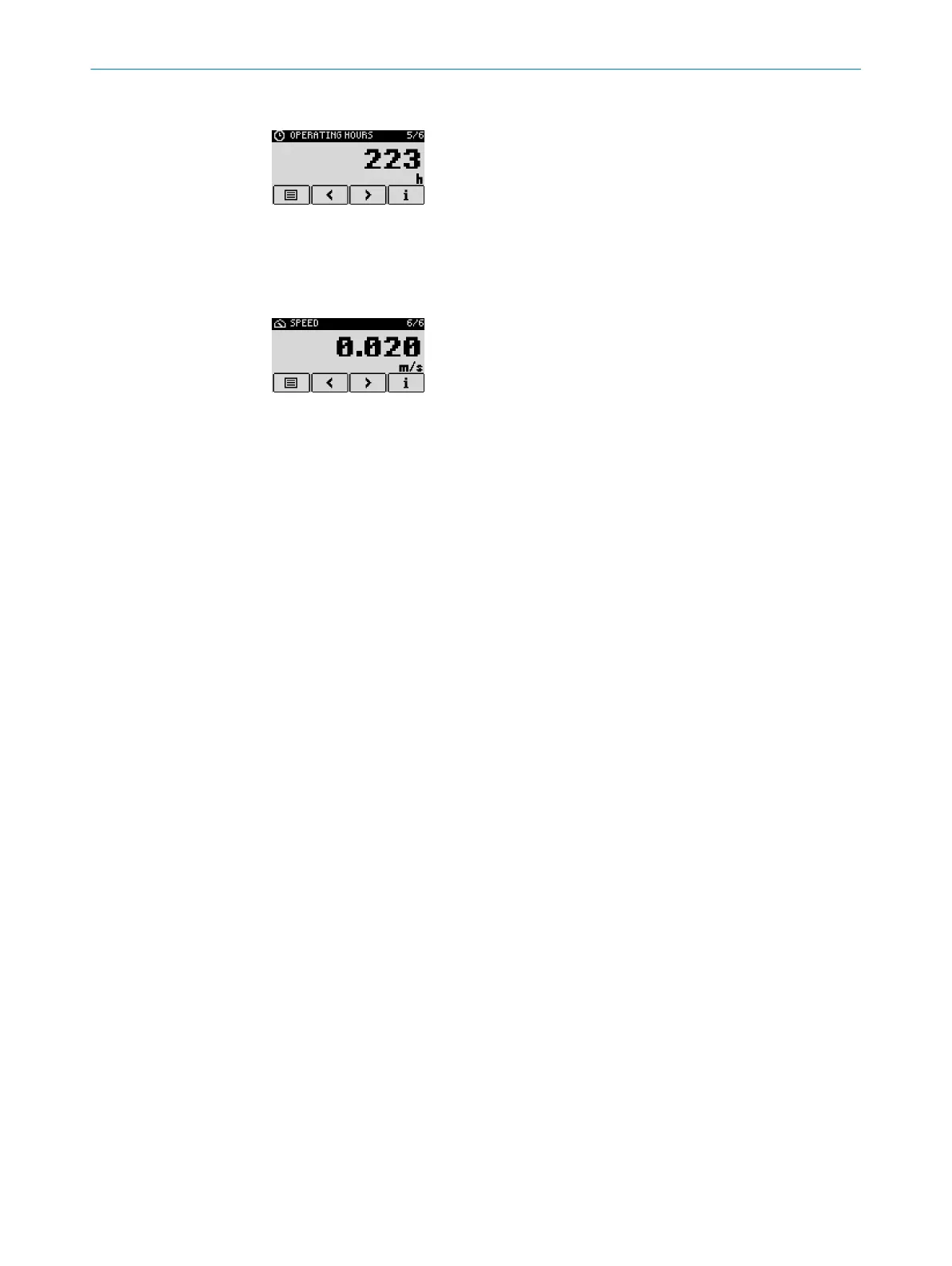
7.3.4 Operating time display
The operating time display depicts the number of operating hours since the first com‐
missioning.
7.3.5 Speed display
The speed display depicts the current measured speed value of the measuring object
relative to the device.
The display can show positive or negative values. Depending on the defined direction of
measurement, this can indicate a movement to or from the device.
7.4
Overview of parameters
7.4.1 Measuring behavior
Basic measuring parameters
•
Measurement mode: "Measuring mode", page 53
•
Measurement cycle time: "Defining the measurement cycle time", page 54
•
Distance offset: "Defining the distance offset", page 54
•
Measurement direction: "Defining the measuring direction", page 55
•
Distance range: "Configuring the distance range", page 58
Improving measurements
•
Measurement cycle time: "Defining the measurement cycle time", page 54
•
Rain and snow filter: "Configuring the rain and snow filter", page 55
•
Fog filter: "Activating/deactivating the fog filter", page 56
•
Kalman filter: "Activating/deactivating the Kalman filter", page 57
•
Averaging filter: "Configuring the distance averaging filter", page 56
•
Echo selection: "Defining the echo selection", page 58
•
Signal level limits: "Configuring signal level range limits", page 59
•
Defining behavior if “no echo” occurs
•
Delay time: "Configuring delay time for "No echo"", page 59
•
Mode: "Defining substitute values for "No echo"", page 60
•
Substitute values: "Configuring user-defined substitute values", page 60
Defining behavior if an error occurs
•
Substitute values: "Configuring user-defined substitute values", page 60
OPERATION 7
8019329/12TZ/2019-03-28 | SICK O P E R A T I N G I N S T R U C T I O N S | DT1000 and DL1000
51
Subject to change without notice

 Loading...


