A
B
1 m
10 m
50 m
100 m
5 m
PWR
In1/Q1
QA/Q2
Q3
Q4
In2
LNK
BUS
3
4
1
2
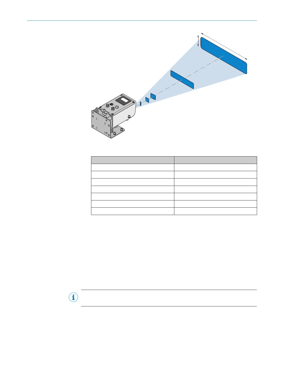
Figure 8: Anisotropy of the light spot
Table 22: Light spot size at different distances
Distance A x B
1 m 20 mm x 5 mm
5 m 20 mm x 20 mm
10 m 25 mm x 35 mm
50 m 50 mm x 150 mm
100 m 80 mm x 290 mm
200 m 140 mm x 570 mm
1500 m 920 mm x 4200 mm
From a distance of 10 m, the light spot size can be determined from the angular
extension of the emitted light of typically 0.6 mrad x 2.8 mrad.
°
A = (0.0006 x distance [mm]) +20 mm
Example for 100 m:
A = (0.0006 x 100,000 mm) +20 mm = 80 mm
°
B = (0.0028 x distance [mm]) +10 mm
Example for 100 m:
B = (0.0028 x 100,000 mm) +10 mm = 290 mm
•
Maintain a sufficient distance to other distance sensors see "Placement of multi‐
ple distance sensors", page 36.
5.3
Select and mount the reflector (DL1000 only)
NOTE
You can find suitable reflectors and suitable reflective tape at www.sick.com/Dx1000.
Reflector tilt
b
To avoid direct surface reflections, mount the reflector with a tilt of approx.
+1° … +3° in one of the 2 axes (horizontal or vertical).
MOUNTING 5
8019329/12TZ/2019-03-28 | SICK O P E R A T I N G I N S T R U C T I O N S | DT1000 and DL1000
33
Subject to change without notice

 Loading...


