Parameter Factory setting
Hysteresis:
0 m/s to 1 m/s
0.05 m/s
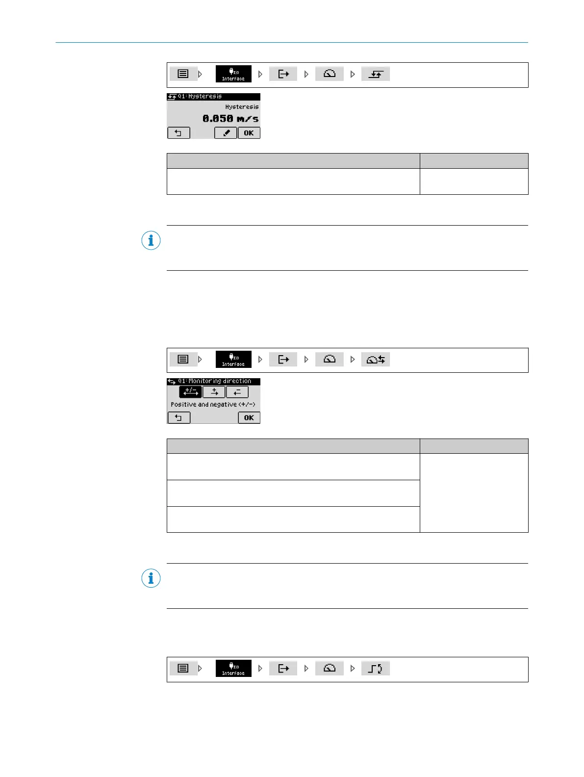
8.3.9 Defining the monitoring direction for the object speed value
NOTE
The procedure for configuring switching outputs Q1 through Q4 is identical. The configu‐
ration is illustrated on switching output Q1.
The “monitoring direction” defines the measuring object direction of movement in rela‐
tion to the device at which a switching event occurs when the object speed is exceeded.
A switching event can be triggered when the switching point for the speed is exceeded
both for an increasing as well as a decreasing distance or if movement goes in both
directions from the measuring object to the device.
Parameter Factory setting
Positive and negative (+/-):
Both directions of movement
Positive and negative (+/-)
Positive (+):
Increasing distance of the measuring object from the device
Negative (-):
Decreasing distance of the measuring object to the device
8.3.10 Defining the switching point active state for the object speed value
NOTE
The procedure for configuring switching outputs Q1 through Q4 is identical. The configu‐
ration is illustrated on switching output Q1.
The active state describes the relationship between the switching state (active or inac‐
tive) and the voltage present on the digital output (high or low) (see "Switching func‐
tions", page 16 / see "Signal inputs/outputs", page 18).
REFERENCE 8
8019329/12TZ/2019-03-28 | SICK O P E R A T I N G I N S T R U C T I O N S | DT1000 and DL1000
65
Subject to change without notice

 Loading...


