The device can be configured so that the desired output values are output in a
continuous data stream or on request:
•
During “continuous data output”, the distance sensor provides distance values or
selected combined data to the interface at defined intervals. The data output is
started automatically after switching on the supply voltage. If the device has been
configured for “data output on request”, continuous data output is started as soon
as the desired output value (distance or combined values) is selected.
•
During “data output on request”, the measured values are only transmitted to the
controller on request. Continuous data transmission in this case must be deacti‐
vated by selecting “REQ”.
Parameter Factory setting
Off:
N
o continuous data output; data output active on request
Off
Distance:
C
ontinuous output of distance values
Distance + speed:
C
ontinuous output of distance and speed values
Distance + service:
C
ontinuous output of distance values and service data
Distance + signal level (RSSI):
C
ontinuous output of distance and signal level values
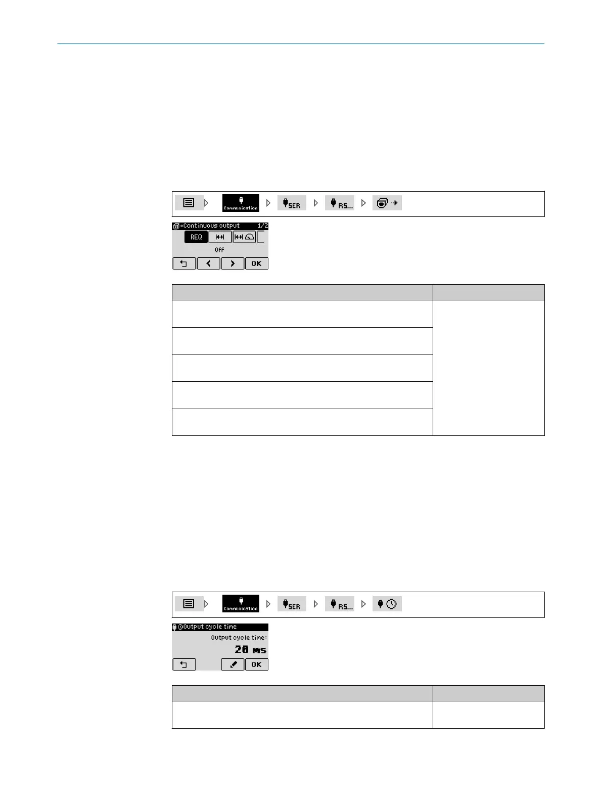
8.5.5 Defining the RS-422 output cycle time
Define the output cycle time of the data to be transmitted for continuous data output
o
ver the serial interface.
The output cycle time should not be shorter than the set measurement cycle time,
since otherwise several identical values are output between two subsequent measure‐
ment cycles.
The minimum achievable output cycle time depends on the data transmission rate, the
RS-422 data protocol (STX/ETX or CRLF) and the selected output value (distance, dis‐
tance+speed etc.), see "RS-422 interface", page 20. If a shorter output cycle time is
set, output is done in accordance with the values specified in table 12.
Parameter Factory setting
Output cycle time:
0 ms ... 1,000 ms
1 ms
REFERENCE 8
8019329/12TZ/2019-03-28 | SICK O P E R A T I N G I N S T R U C T I O N S | DT1000 and DL1000
73
Subject to change without notice

 Loading...


