8.3.4 Defining the switching window for the distance value
NOTE
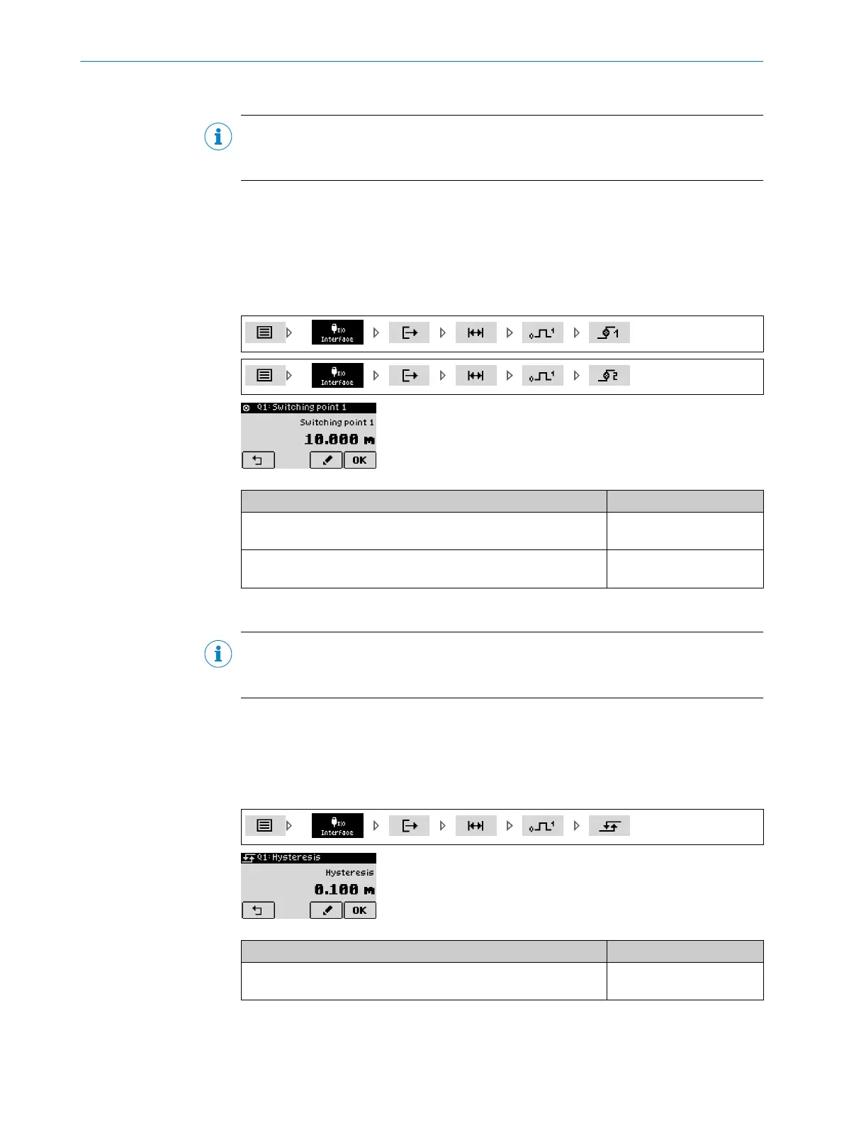
The procedure for configuring switching outputs Q1 through Q4 is identical. The configu‐
ration is illustrated on switching output Q1.
The switching state is active if the distance output value is between switching point SP1
and switching point SP2.
Switching points SP1 and SP2 respectively designate the distance value at which the
switching event is triggered (see "Switching functions", page 16).
The values of the switching points refer to the output distance value = measurement
direction x measured distance value + distance offset.
Parameter Factory setting
Switching point 1:
-4500 m to 4500 m
10 m
Switching point 2:
-4500 m to 4500 m
20 m
8.3.5 Defining the switching window hysteresis for the distance value
NOTE
The procedure for configuring switching outputs Q1 through Q4 is identical. The configu‐
ration is illustrated on switching output Q1.
Unwanted switching can be prevented by entering a hysteresis if the determined dis‐
tance value fluctuates around the set switching points (see "Switching functions",
page 16).
The switching hysteresis for the “Window” switching function is the same for both SP1
and SP2 window limits.
Parameter Factory setting
Hysteresis:
0 m to 1500 m
0.1 m
REFERENCE 8
8019329/12TZ/2019-03-28 | SICK O P E R A T I N G I N S T R U C T I O N S | DT1000 and DL1000
63
Subject to change without notice

 Loading...


