6.3 Connecting the device electrically
NOTE
The connection diagram, and information on inputs and outputs can be found on the
type label on the device.
1. Ensure the voltage supply is not connected.
2. Connect the device according to the connection diagram.
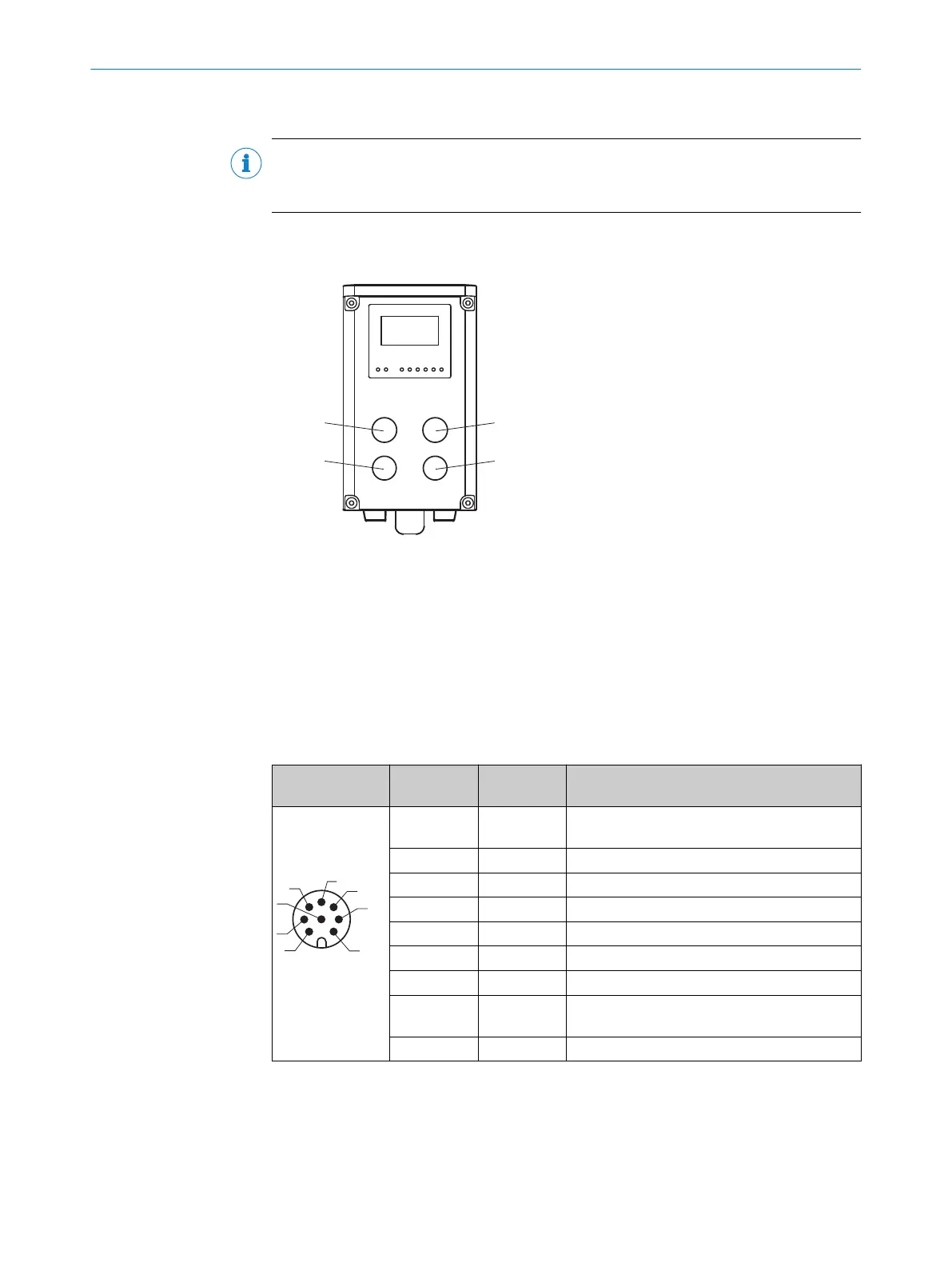
Figure 21: Position of the electrical connections
1
Power, RS-422/SSI, Q1/In1, QA/Q2
2
Auxilliary
3
not assigned, do not remove (glued) protection cap!
4
Ethernet
6.3.1 Pin assignment
1 Power, RS-422/SSI, Q1/In1, QA/Q2
Table 25: Pin assignment connection 1: Power/RS422/SSI/analog
Male/female
connector
Contact Short form Signal description
M12 male con‐
nector, 8-pin A-
coded
1 Q1/In1 Push-pull digital output, can be switched to dig‐
ital input (internal pull-down)
2 L+ Supply voltage: +18 V … +30 V DC
3 RX-/CLK- RS-422 data input neg/SSI Clk neg
4 RX+/CLK+ RS-422 data input pos/SSI Clk pos
5 TX-/Data- RS-422 data output neg/SSI data neg
6 TX+/Data+ RS-422 data output pos/SSI data pos
7 M Supply voltage: 0 V
8 QA/Q2 Push-pull digital output, can be switched to
current output
Thread Cable shield (housing)
ELECTRICAL INSTALLATION 6
8019329/12TZ/2019-03-28 | SICK O P E R A T I N G I N S T R U C T I O N S | DT1000 and DL1000
45
Subject to change without notice

 Loading...


