Additional information and a description of communication with the CoLa-A SICK proto‐
col (ASCII values) used with the device can be found in the “Dx1000 Telegram Listing”
(English, no. 8021820) technical information publication available at www.sick.com/
Dx1000.
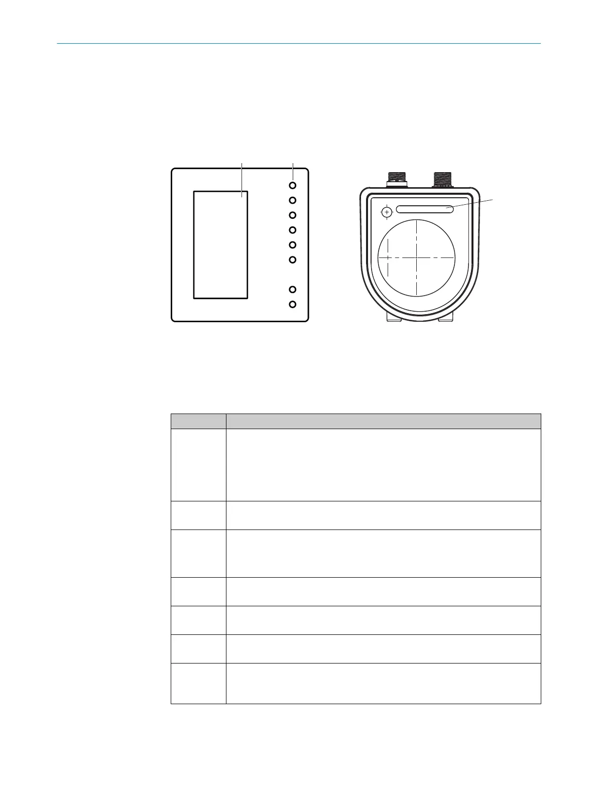
3.8 Display and operating elements
1
PWR
In1/Q1
QA/Q2
Q3
Q4
In2
LNK
BUS
2
3
Figure 6: Display and operating elements
1
Touch display
2
LEDs
3
Status indicator
LEDs/Operating and status display
LED Description
LED PWR
and LED
operating
and status
display
■
LED off: no operation, no supply voltage connected
■
Green LED: interference-free operation
■
Orange LED flashing: warning (device status via SOPAS ET or device status
double word, see table 33, page 93)
■
Red LED flashing: error (device status via SOPAS ET or device status double
word, see table 33, page 93)
LED In1/Q1
■
LED off: digital output or digital input deactivated
■
Orange LED: digital output or digital input active
LED QA/Q2
■
LED off: digital output deactivated or analog output signal above or below the
valid current levels (4 mA … 20 mA)
■
Orange LED: digital output active or analog output signal within the valid cur‐
rent levels
LED Q3
■
LED off: digital output deactivated
■
Orange LED: digital output active
LED Q4
■
LED off: digital output deactivated
■
Orange LED: digital output active
LED In2
■
LED off: digital input deactivated
■
Orange LED: digital input active
LED LNK
■
LED off: No Ethernet connection available
■
Green LED: Ethernet connection available
■
LED flashes green: Ethernet data transmission active
PRODUCT DESCRIPTION 3
8019329/12TZ/2019-03-28 | SICK O P E R A T I N G I N S T R U C T I O N S | DT1000 and DL1000
27
Subject to change without notice

 Loading...


