Communication modules
6.3 GDM memory module CP52M0
SIMATIC TDC hardware
System Manual, 08/2017, A5E01114865-AL
139
Status and fault displays
Status displays for CP52M0
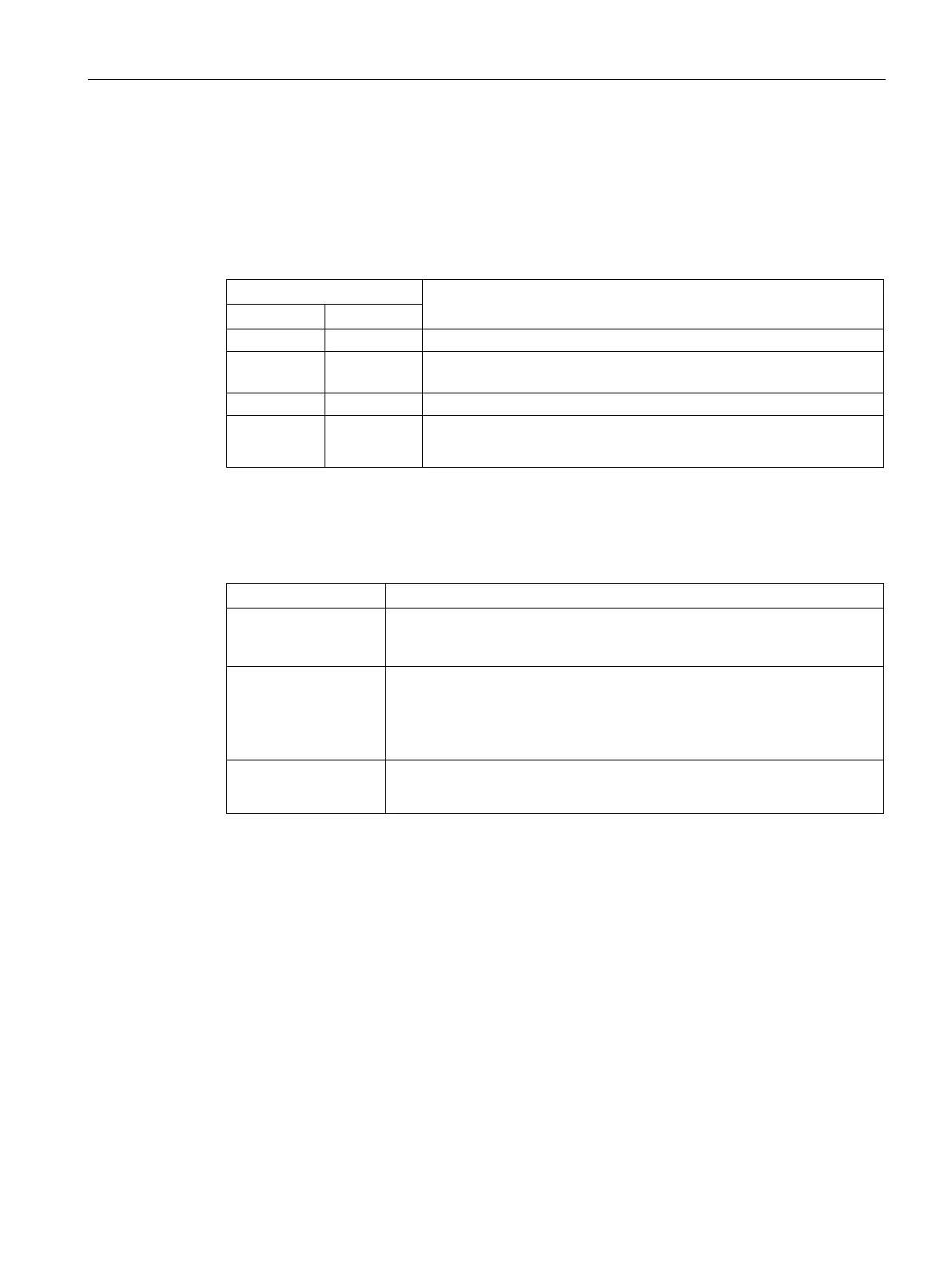
Table 6- 10 LED status displays for the CP52M0 GDM memory module
Status of the CP52M0 module
Off On All FPGAs in the GDM rack (CP52M0 and CP52IO) are parameter-
ized; the module is initialized
On Off The module i initialized and operates without errors
On On After 3.3 V or 2.5 V voltage failure
• Hardware failure => Switch off the rack and replace CP52M0
Status displays at the digital outputs
Table 6- 11 Status displays at the digital outputs of CP52M0
DA01 to 11 Indicate the CP52IO slot (slots 2-12) from which the operating state of the
four fiber-optic interfaces is displayed on DA12-DA15. The operating state
display of the individual CP52IO modules is cycled at seconds intervals.
DA12 to 15 Indicate the operating state of the four fiber-optic interfaces of a CP52IO
(DA12 fiber-optic interface 1, DA13 fiber-optic interface 2, etc.).
• Logical status "1" => FOC interface is OK
• Logical status "0" => Error at FOC interface, or CP52IO is missing
DA16
• Logical status "1" => RUN operating state
• Logical status "0" => STOP operating state

 Loading...


