Rack
3.1 Rack UR6021 (6DD1682-0CH3)
SIMATIC TDC hardware
System Manual, 08/2017, A5E01114865-AL
43
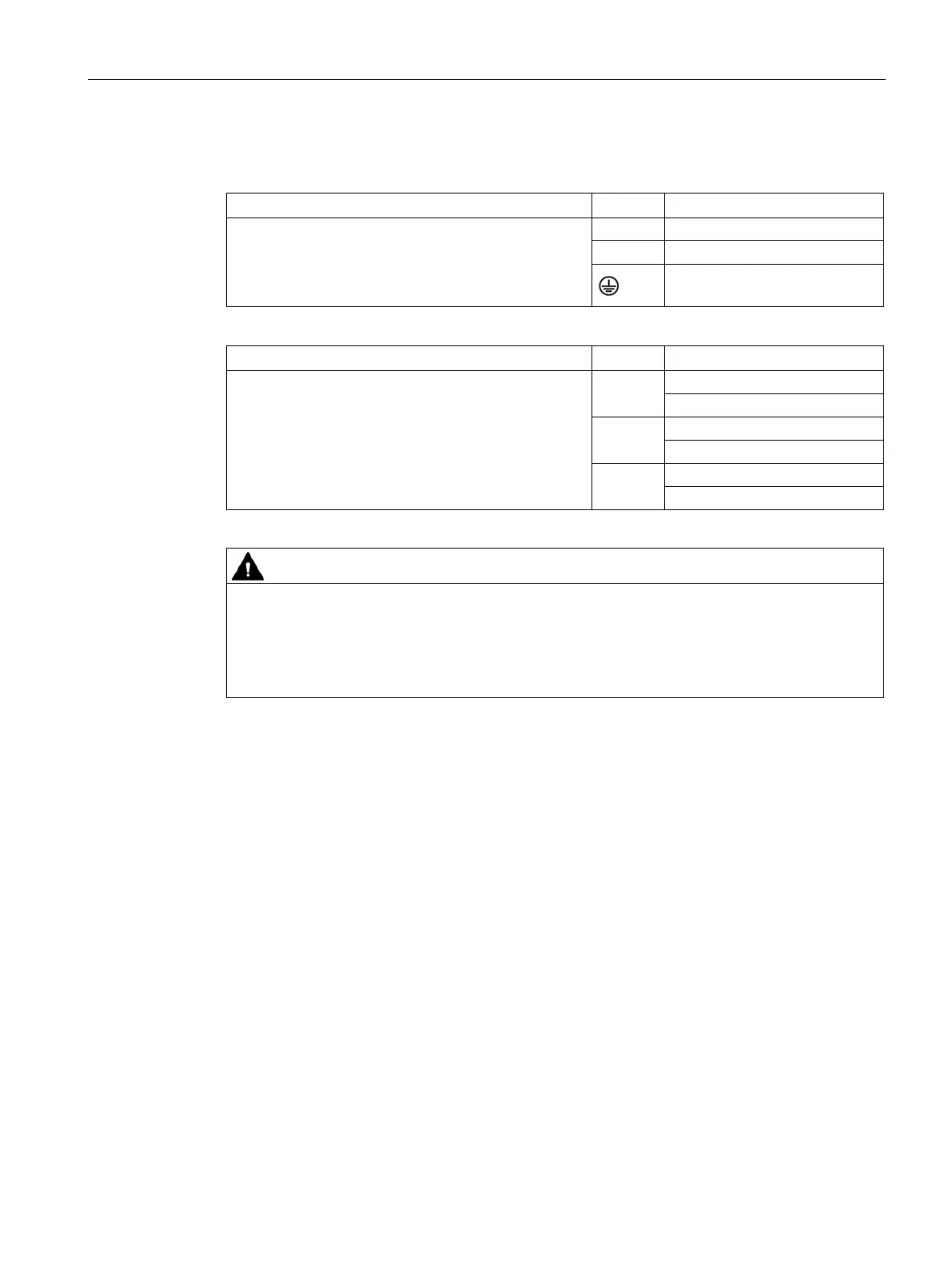
Screw terminal with screw lock (3x1.5 mm
2
, stranded
wires dressed with wire end ferrules with insulating
collars)
Make sure that the strain relief is properly mounted.
N Neutral conductor
PE/ground conductor
Cage clamp terminal (0.5 mm
2
–-1.5 mm
2
, stripped
length 7 mm, stranded wires dressed with wire end
ferrules with insulating collars)
Make sure that the strain relief is properly mounted.
1, 2
SYSFAIL signaling contact
3, 4
5, 6
FAN FAIL signaling contact
The PE/ground conductor must be connected to the power supply.
The PE/ground terminal on the rack (min. 6 mm
2
) is inappropriate.
The PE/ground conductor must be green with yellow stripe (green/yellow).
Ungrounded installation of the rack is not planned.

 Loading...


