Rack
3.2 Rack UR5213 (6DD1682-0CH2)
SIMATIC TDC hardware
56 System Manual, 08/2017, A5E01114865-AL
Status and fault displays
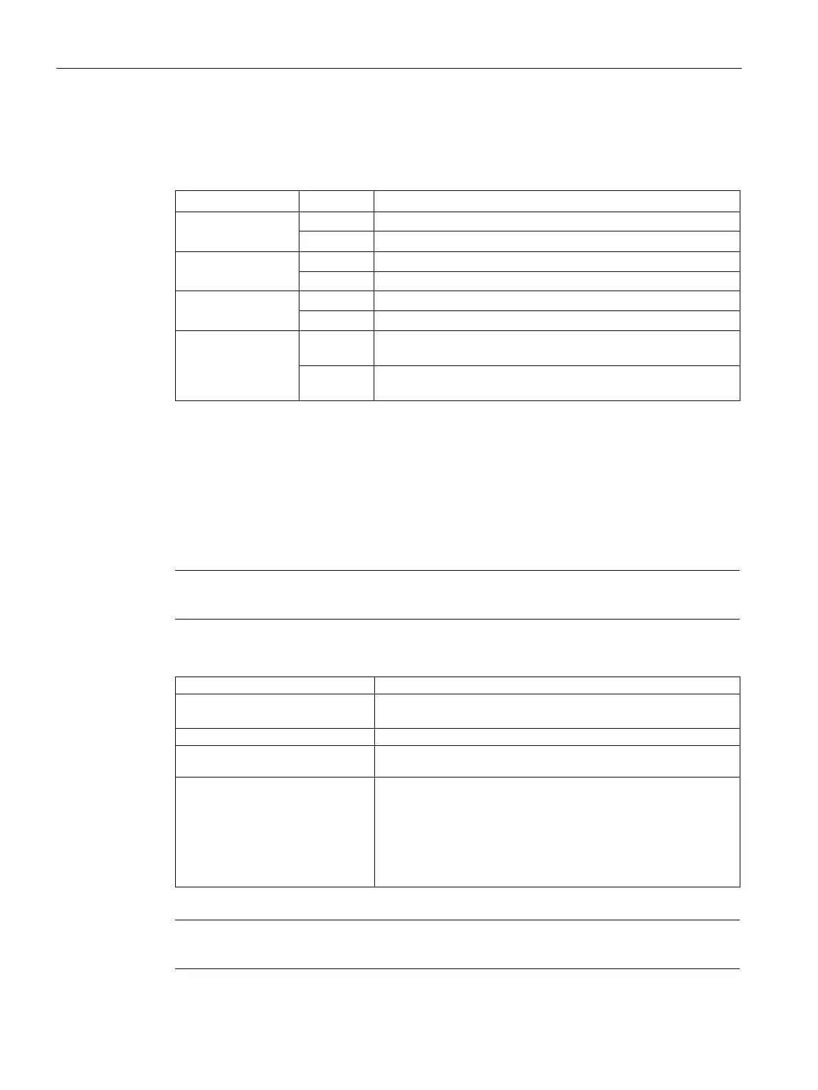
Table 3- 2 Status displays for UR5213
(green or red)
red is on fault (refer to voltage monitoring)
fault (at least one fan has failed)
(yellow)
On Shutdown on failure of two fans (corresponds to the OFF posi-
Flashing Shutdown on failure of one fan (corresponds to the ON position
Power supply
Mains connection
Mains is connected to the 3-pin screw terminal block on the right side of the power supply
unit.
Note
Always use the integrated strain relief for the mains cable on the 3
-pin screw terminal block.
The pin assignment is printed onto the front panel.
Test voltage
Primary ↔ PE
800 W (apparent power approx. 835 VA)
3x1.5 mm2 (stranded wires dressed with wire end ferrules with
ISO insulating collars)
(dimensioning)
Is = <40 A (inrush peak)
The power supply is equipped with an internal 20 A fuse. This
means that only the mains supply has to be fused. It is recom-
mended to use a standard 16 A thermo magnetic circuit-breaker
(B characteristic).
Alternatively, a slow-acting fuse may be used.
Note
A mains disconnect unit must be provided during installation of the rack.

 Loading...


