Interface module
7.1 Interface module SB10
SIMATIC TDC hardware
System Manual, 08/2017, A5E01114865-AL
177
The status of each of the 8 signals (1...8) is displayed by means of a yellow LED. Each
signal is provided a screw terminal on the two terminal blocks X2:
● Terminals 1 to 8 for digital signals
● Terminals 51 to 58 for reference points
Reference potential of the signals
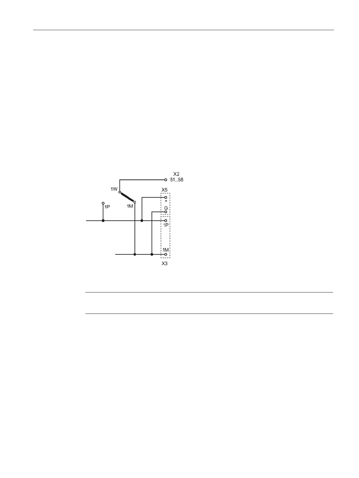
The reference points of the signals may be derived from 1M or 1P potential. The polarity is
selected on the module by means of soldering bridge:
Figure 7-1 Soldering bridge for setting the signal reference points
-1W is inserted in the factory

 Loading...


