Tuning
9.8 Gain switching
SINAMICS V90, SIMOTICS S-1FL6
330 Operating Instructions, 04/2019, A5E36037884-007
Note
The Gain Switching function is not
available in
mode (torque control mode).
-tuning must be disabled so that the function of gain switching can be
With this function, you can implement the following operations:
● Increase the gains during servo lock and decrease gains to reduce noise during rotation.
● Increase the gains during settling to shorten the stop settling time.
● Switch between two groups of gains using an external signal (G-CHANGE) to ensure
stability of the servo system because the load inertia moment ratio varies greatly during a
stop (for example, a large load is mounted on a carrier).
Selection of a gain switching mode
Five gain switching modes in total are available:
● Gain switching disabled
● Gain switching using digital input signal (G-CHANGE)
● Gain switching using position deviation
● Gain switching using position setpoint frequency
● Gain switching using actual speed
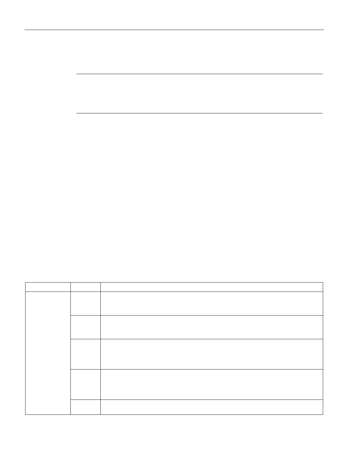
You can select one of the five modes by setting parameter p29130:
p29130 0 (default) The function of gain switching is disabled.
Only the first group of gains is valid and the function of PI to P switching of speed controller
1 Gain switching using digital input signal (G-CHANGE).
When G-CHANGE is 0, the first group of gains is selected; when G-CHANGE is 1, the
2 Gain switching using position deviation.
In the position control mode, gain switching can be decided by position deviation. If the
position deviation is less than preset value, the first group of gains is selected; otherwise,
the second one is selected.
3 Gain switching using position setpoint frequency.
In the position control mode, gain switching can also be decided by position setpoint fre-
quency. If the position setpoint frequency is less than preset value, the first group of gain is
selected; otherwise, the second one is selected.
4 In the speed control mode, gain switching can be decided by actual speed. If the actual
speed is below preset value; otherwise, the second one is selected.

 Loading...


