EasyManuals Logo

Siemens SINAMICS V90 User Manual

Siemens SINAMICS V90
432 pages
To Next Page IconTo Next Page
To Previous Page IconTo Previous Page
Page #415 background imageLoading...
Page #415 background image
Appendix
A.1 Cable assembly
SINAMICS V90, SIMOTICS S-1FL6
Operating Instructions, 04/2019, A5E36037884-007
413
A.1.1.3
Brake terminal assembly
The assembly of a brake terminal follows the procedure as described for a power terminal of
the 200 V variant servo drive. See Section "Power terminal assembly (Page 411)" for details.
A.1.1.4
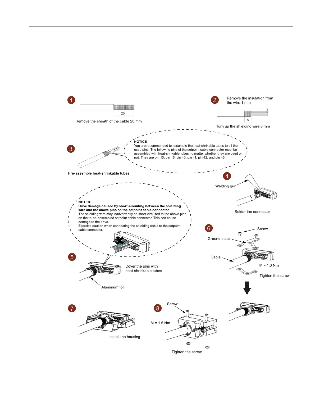
Setpoint connector assembly

Table of Contents

Other manuals for Siemens SINAMICS V90

Questions and Answers:

Question and Answer IconNeed help?

Do you have a question about the Siemens SINAMICS V90 and is the answer not in the manual?

Siemens SINAMICS V90 Specifications

General IconGeneral
Power Range0.05 kW to 7.0 kW
Protection ClassIP20
CommunicationUSS/Modbus RTU
FeedbackIncremental encoder
Input Voltage1AC 200 V to 240 V, 3AC 380 V to 480 V
Control ModesPosition, Speed, Torque
Operating Temperature0 °C to +40°C
Storage Temperature-40°C to +70°C
Relative Humidity5% to 95% (non-condensing)
AltitudeUp to 1000 m above sea level

Related product manuals