Cross-point
control block
Select DSK5 to DSK8
signals in the 2nd row.
Select DSK1 to DSK8
using the next
transition selection
buttons.
Set the DSK1 to DSK8
key priority.
Disabled operation/setting
Engineering Setup >Switcher
>Output >4:3 Crop
Engineering Setup >Switcher
>Output >Multi Viewer >Source/
Output Assign
• When setting the [Src No] parameter: DME Monitor Video, DME
Monitor Key, M/E-2, Primary 33 to 48 signal selection
• When setting the [Output No] parameter: Output 13 to 32 selection
Engineering Setup >Switcher
>Output >FC Output Select
Output 13 to 32 selection
Engineering Setup >Switcher
>Output >Aux Mix
Engineering Setup >Switcher
>Transition
Engineering Setup >Switcher
>Transition >Preset Color Mix
• M/E-2 settings
• [Key5] to [Key8] selection
Engineering Setup >Switcher
>Transition >Transition Curve
Engineering Setup >Switcher >Key/
Wipe/FM/CCR
Engineering Setup >Switcher >Key/
Wipe/FM/CCR >Show Key
Engineering Setup >Switcher >Link
>Internal Bus Link >Link Bus Select
• Selection of items related to M/E-2
• Selection of items related to P/P Key5 to 8
Engineering Setup >Switcher >Link
>GPI Link >GPI Link Adjust
• M/E-2 Auto Trans, M/E-2 Cut selection on video/button display
• M/E-2 bus settings on bus display
Engineering Setup >Switcher >Link
>M/E Link
Engineering Setup >Switcher >Link
>Key Transition Link
• Selection of items related to M/E-2
• Selection of items related to P/P Key5 to 8
Engineering Setup >Switcher
>Device Interface >GPI Input
• [M/E-2] selection
• Selection of following items on [P/P] (x=5 to 8):
DSKx Cut, DSKx Auto Trans, DSKx SS ? Recall
Engineering Setup >Switcher
>Device Interface >GPI Output
• [M/E-2] selection
• Selection of following items when Trigger Type is not set to Status in
[P/P] (x=5 to 8): DSKx Cut, DSKx Auto Trans, DSKx SS ? Recall
• Selection of following items when Trigger Type is set to Status in [P/P]
(x=5 to 8): DSKx On
Engineering Setup >DME >Device
Interface >DME1 GPI Input
a) The same conditions apply to the Key2 to Key4 and DSK2 to DSK4 menus.
b) For Key3, Key4, DSK3 and DSK4, “Processed Key” is displayed instead of “Processed Key/Resizer.”
c) For details about patterns that can be selected,
1
“Types of DME Wipe Pattern” (p. 111).
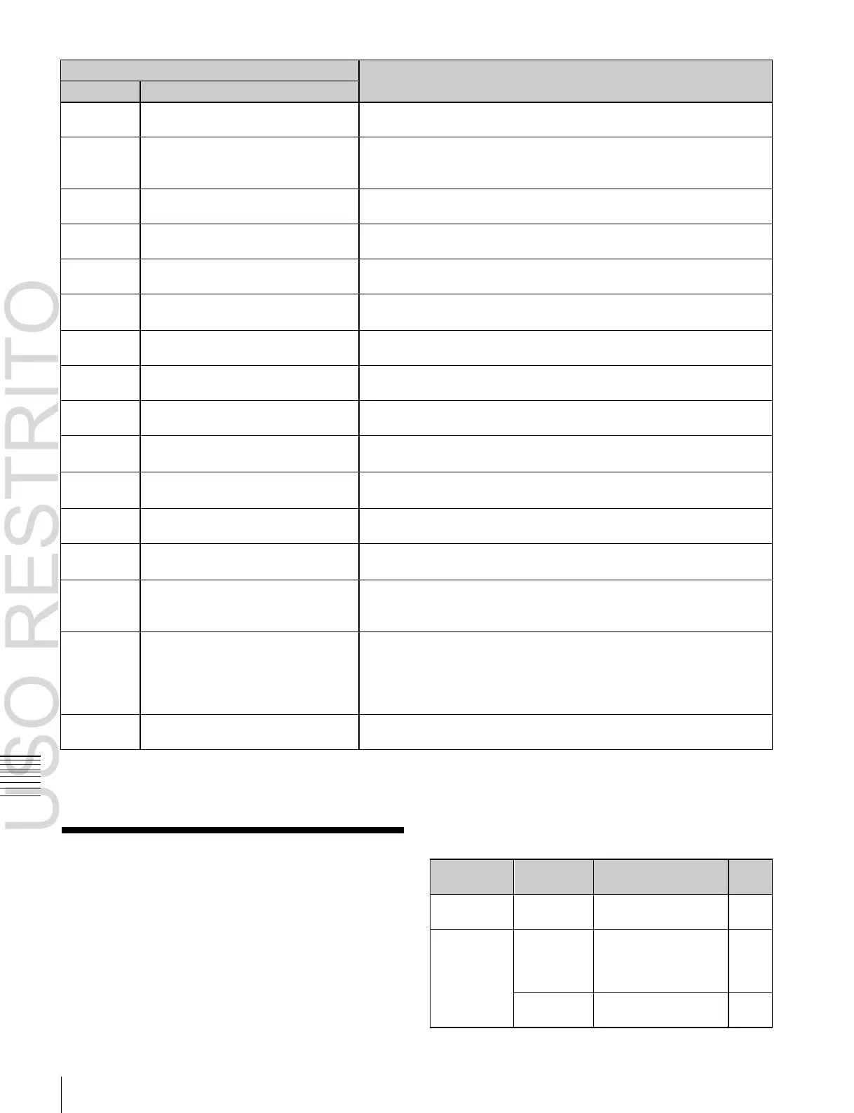
8-Keyer Operation
The key operation description in this User’s Guide is
mainly geared to 4-keyer operation.
Using the MVS-6530 (3M/E processor), the PGM/PST
bank can be operated using eight keyers (DSK1 to DSK8).
The operations required for eight keyers are described
below.
8-keyer operation list
 Loading...


