2-14. DCP-64 Board
Preparation
1. Remove the bottom panel assembly. (Refer to “2-5. Bottom Panel Assembly”)
2. Remove the inside panel assembly. (Refer to “2-6-1. Inside Panel Assembly”)
3. Remove the outside panel assembly. (Refer to “2-7-1. Outside Panel Assembly”)
4. Remove the rear panel assembly. (Refer to “2-8. Rear Panel Assembly”)
5. Remove the IO block. (Refer to “2-10. IO Block”)
6. Remove the handle assembly. (Refer to “2-11-1. Handle Assembly”)
Procedure
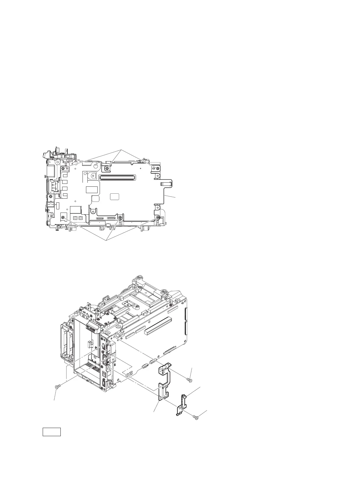
1. Remove the six screws to detach the heat spreader DCP assembly.
P2 x 4
Heat spreader DCP assembly
P2 x 4
2. Remove the screw (P2 x 4) to detach the USB GND plate.
3. Remove the two screws (P1.7 x 4) and the screw (P2 x 4) to detach the HDMI bracket.
(a)
P2 x 4
USB GND plate
HDMI bracket
(b)
P2 x 4
(c)
P1.7 x 4
Note
When installing the USB GND plate and the HDMI bracket, tighten screws (a) to (c) in alphabetical order.
4. Disconnect the five fine-wire coaxial cables from the five connectors on the DCP-64 board.
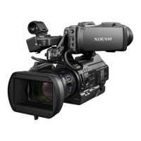
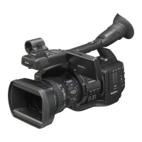
PMW-300
2-45
 Loading...