4-66 FI SYSTEM DIAGNOSIS
“49” (P1656) PAIR CONTROL SOLENOID VALVE CIRCUIT MALFUNCTION
INSPECTION
NOTE:
After repairing the trouble, clear the DTC using SDS tool.
(4-24)
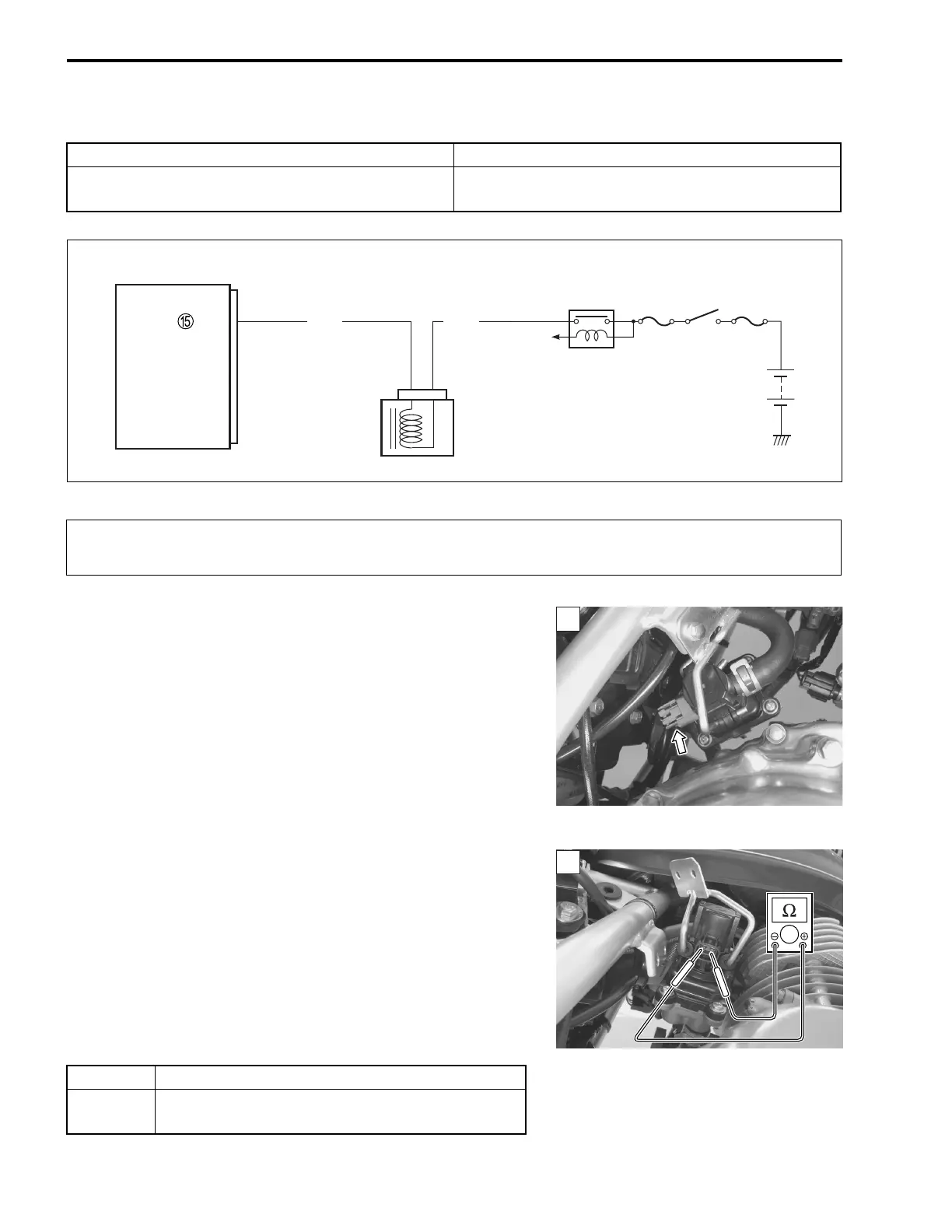
Step 1
1) Turn the ignition switch OFF.
2) Check the PAIR control solenoid valve coupler for loose or
poor contacts.
If OK, then measure the PAIR control solenoid valve resis-
tance.
3) Remove the PAIR control solenoid valve. (11-7)
4) Measure the resistance between terminals.
PAIR control solenoid valve resistance:
Approx. 22
Ω
at 20 °C (68 °F)
(Terminal – Terminal)
09900-25008: Multi circuit tester set
Tester knob indication: Resistance (Ω)
Is the resistance OK?
DETECTED CONDITION POSSIBLE CAUSE
PAIR control solenoid valve voltage is not input to
ECM.
• PAIR control solenoid valve circuit open or short
• PAIR control solenoid valve malfunction
Ignition switch
Side-stand
relay
To side-stand
switch
ECM
PAIR
O/WB/G
PAIR control solenoid
valve
When using the multi circuit tester, do not strongly touch the terminal of the ECM coupler with
a needle-point probe to prevent the terminal damage or terminal bend.
1
YES Go to Step 2.
NO
Replace the PAIR control solenoid valve with a
new one.
1

 Loading...