Home
Suzuki
Motorcycle
TU250X
Suzuki TU250X User Manual
5
of 1
of 1 rating
370 pages
Give review
Manual
Specs
To Next Page
To Next Page
To Previous Page
To Previous Page
Loading...
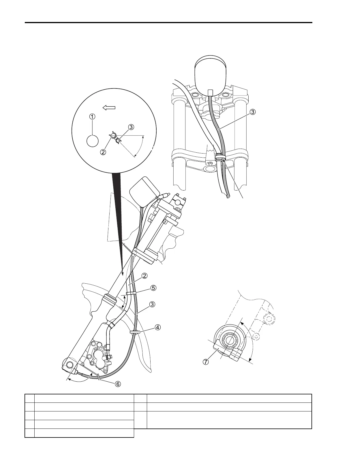
10-16 SERVICING INFORMATION
SPEEDOMETER CABLE ROUTING
1
Front f
or
k
6
Cable guide
2
Brake hose
7
Speedometer gearbox
3
Speedometer cable
1*
Bind the speedometer cable and hose guide with the clamp
.
Cut off the e
xcess end of clamp.
4
Cable guide
5
Clamp
FWD
45 ± 15˚
*1
90 ± 5˚
90 ± 5˚
335
337
Table of Contents
General Information 1
11
Table of Contents
11
Warning/Caution/Note
12
General Precautions
12
Suzuki Tu250X ('09-Model)
14
Serial Number Location
14
Fuel and Oil Recommendation
15
Fuel
15
Engine Oil
15
Brake Fluid
15
Front Fork Oil
15
Break-In Procedures
15
Information Labels
16
Specifications
17
Dimensions and Curb Mass
17
Engine
17
Drive Train
17
Chassis
18
Electrical
18
Capacities
18
Periodic Maintenance
19
Periodic Maintenance Schedule
20
Periodic Maintenance Chart
20
Lubrication Points
21
Maintenance and Tune-Up Procedures
22
Air Cleaner
22
Valve Clearance
23
Spark Plug
25
Throttle Cable Play
26
Engine Idle Speed
26
Fuel Line
27
Clutch Cable Play
27
Pair (Air Supply) System
27
Engine Oil and Oil Filter
28
Drive Chain
29
Brakes
32
Steering
36
Tires
37
Front Fork
38
Rear Suspension
38
Exhaust Pipe Bolts and Muffler Mounting Bolts
39
Chassis Bolts and Nuts
40
Compression Pressure Check
42
Compression Test Procedure
42
Oil Pressure Check
43
Oil Pressure Test Procedure
43
Sds Check
44
Engine
48
Engine Components Removable with Engine in Place
49
Engine Removal and Installation
50
Removal
50
Installation
55
Engine Disassembly
58
Engine Components Inspection and Service
72
Cylinder Head Cover
72
Cylinder Head
73
Camshaft
82
Cylinder
82
Piston
83
Conrod and Crankshaft
85
Starter Clutch and Starter Driven Gear Bearing
87
Balancer Driven Gear
88
Generator
89
Gearshift Shaft
89
Oil Filter
90
Oil Strainer
90
Oil Pump
91
Transmission
92
Clutch
95
Crankcase Bearing and Oil Seal
96
Clutch Release Camshaft
101
Clutch Cover
102
Engine Reassembly
103
Fi System Diagnosis
122
Precautions in Servicing
124
Electrical Parts
124
Fuse
125
Switch
125
Ecm/Various Sensors
125
Electrical Circuit Inspection Procedure
127
Using the Multi Circuit Tester
130
Fi System Technical Features
131
Injection Time (Injection Volume)
131
Compensation of Injection Time (Volume)
132
Injection Stop Control
132
Fi System Parts Location
133
Fi System Wiring Diagram
134
Ecm Terminal
135
Self-Diagnosis Function
136
User Mode
136
Dealer Mode
137
Fail-Safe Function
138
Fi System Troubleshooting
139
Self-Diagnostic Procedures
141
Use of Sds Diagnostic Procedures
144
Use of Sds Diagnosis Reset Procedure
145
Show Data When Trouble (Displaing Data at the Time of Dtc)
146
Malfunction Code and Defective Condition
147
12" (P0335) Ckp Sensor Circuit Malfunction
150
13" (P0105-H/L) Iap Sensor Circuit Malfunction
152
14" (P0120-H/L) Tp Sensor Circuit Malfunction
157
15" (P0115-H/L) Et Sensor Circuit Malfunction
162
21" (P0110-H/L) Iat Sensor Circuit Malfunction
166
23" (P1651-H/L) to Sensor Circuit Malfunction
170
24" (P0351) Ignition System Malfunction
173
28" (P1655) Stv Actuator Circuit Malfunction
174
29" (P1654-H/L) Stp Sensor Circuit Malfunction
177
32" (P0201) Fuel Injector Circuit Malfunction
181
41" (P0230-H/L) Fp Circuit Malfunction
183
42" (P01650) Ig Switch Circuit Malfunction
184
44" (P0130) Ho2 Sensor (Ho2S) Circuit Malfunction
185
49" (P1656) Pair Control Solenoid Valve Circuit Malfunction
187
Sensors
189
Ckp Sensor Inspection
189
Ckp Sensor Removal and Installation
189
Iap Sensor Inspection
189
Iap Sensor Removal and Installation
189
Tp Sensor Inspection
189
Tp Sensor Removal and Installation
189
Tps Adjustment
190
Et Sensor Inspection
191
Et Sensor Removal and Installation
191
Iat Sensor Inspection
191
Iat Sensor Removal and Installation
191
To Sensor Inspection
192
To Sensor Removal and Installation
192
Stp Sensor Inspection
192
Stp Sensor Removal and Installation
192
Stp Sensor Adjustment
192
Ho2 Sensor Inspection
192
Ho2 Sensor Removal and Installation
193
Fuel System and Throttle Body
194
Fuel Delivery System
195
Fuel System
196
Fuel Tank Removal
196
Fuel Tank Installation
196
Fuel Pressure Inspection
197
Fuel Pump Inspection
198
Fuel Discharge Amount Inspection
198
Fuel Pump Construction
199
Fuel Pump Removal and Disassembly
200
Fuel Mesh Filter Inspection
201
Fuel Pump Reassembly and Installation
202
Throttle Body
203
Construction
203
Throttle Body Removal
204
Throttle Body Disassembly
205
Throttle Body Cleaning
207
Throttle Body Inspection
207
Throttle Body Reassembly
208
Throttle Body Installation
210
Stp Sensor Adjustment
211
Fast Idle
212
Fuel Injector Removal
212
Fuel Injector Inspection
212
Fuel Injector Installation
212
Exhaust System
213
Exhaust System
214
Removal
214
Inspection
216
Installation
216
Chassis
221
Exterior Parts
223
Removal
223
Installation
223
Front Wheel
224
Construction
224
Removal
224
Inspection and Disassembly
226
Reassembly and Installation
227
Front Brake
231
Construction
231
Brake Pad Replacement
232
Brake Fluid Replacement
233
Brake Caliper Removal and Disassembly
233
Brake Caliper Inspection
234
Caliper Reassembly and Installation
235
Brake Disc Inspection
237
Master Cylinder Removal and Disassembly
237
Master Cylinder Inspection
238
Master Cylinder Reassembly and Installation
239
Handlebars
241
Construction
241
Removal
241
Inspection
242
Installation
243
Front Fork
245
Construction
245
Removal and Disassembly
246
Inspection
248
Reassembly and Installation
249
Steering
253
Construction
253
Removal and Disassembly
253
Inspection
256
Reassembly and Installation
257
Rear Brake Pedal Removal
262
Rear Brake Pedal Installation
262
Rear Shock Absorber
263
Construction
263
Removal
263
Inspection
264
Installation
264
Rear Suspension Setting
264
Rear Wheel
265
Construction
265
Removal
266
Inspection and Disassembly
268
Swingarm
273
Construction
273
Removal
274
Reassembly
276
Installation
278
Tire and Wheel
279
Tire Removal
279
Inspection
279
Tire Installation
280
Electrical System
282
Cautions in Servicing
284
Connector
284
Coupler
284
Clamp
284
Fuse
284
Switch
285
Semi-Conductor Equipped Part
285
Battery
285
Connecting the Battery
285
Wiring Procedure
286
Using the Multi Circuit Tester
286
Location of Electrical Components
287
Charging System
289
Troubleshooting
289
Inspection
290
Starter System and Side-Stand/Ignition Interlock System
293
Troubleshooting
293
Starter Motor Removal
294
Starter Motor Disassembly
295
Starter Motor Inspection
296
Starter Motor Reassembly
297
Starter Motor Installation
298
Starter Relay Inspection
299
Side Stand/Ignition Interlock System Parts Inspection
300
Ignition System
302
Troubleshooting
303
Inspection
304
Speedometer
307
Removal and Disassembly
307
Inspection
308
Lamps
311
Headlight
311
Brake Light/Taillight
313
Turn Signal Light
314
Relays
315
Turn Signal/Side-Stand Relay
315
Main Relay
315
Check Relay
315
Switch
316
Ignition Switch Removal
316
Ignition Switch Installation
316
Switch Inspection
317
Battery
318
Specifications
318
Initial Charging
318
Servicing
320
Recharging Operation
320
Servicing Information
321
Troubleshooting
322
Fi System Malfunction Code and Defective Condition
322
Engine
322
Chassis
328
Brakes
329
Electrical
330
Battery
331
Wiring Harness, Cable and Hose Routing
332
Wiring Harness Routing
332
Throttle Cable Routing
335
Speedometer Cable Routing
336
Front Brake Hose Routing
337
Pair (Air Supply) System Hose Routing
338
Cylinder Head Rubber Pad Installation
339
Exhaust System Construction
339
Throttle Body and Fuel Pump Installation
340
Rear Brake Pedal Installation
341
Torque Link Installation
341
Side-Stand Installation
342
Front Turn Signal Light Installation
343
Rear Turn Signal Light Installation
343
Special Tools
344
Tightening Torque
347
Engine
347
Fi System and Intake Air System
348
Chassis
348
Tightening Torque Chart
349
Service Data
350
Emission Control Information
359
Emission Control Systems
360
Fuel Injection System
360
Crankcase Emission Control System
361
Exhaust Emission Control System
362
Ho2 Sensor Inspection
363
Ho2 Sensor Removal and Installation
363
Noise Emission Control System
363
Pair (Air Supply) System and Emission Control System Inspection
364
Pair Hoses
364
Pair Reed Valve
364
Pcv Hose
365
Pair Control Solenoid Valve
365
Pair (Air Supply) System Diagram
367
Pair (Air Supply) System Hose Routing
367
5
Based on 1 rating
Ask a question
Give review
Questions and Answers:
Need help?
Do you have a question about the Suzuki TU250X and is the answer not in the manual?
Ask a question
Suzuki TU250X Specifications
General
Brand
Suzuki
Model
TU250X
Category
Motorcycle
Language
English
Related product manuals
Suzuki T250
32 pages
Suzuki T350
32 pages
Suzuki TS200R
195 pages
Suzuki TL1000S
89 pages
Suzuki TS400 1974
44 pages
Suzuki TM400 1971
44 pages
Suzuki TM400 1974
44 pages
Suzuki FZ50 T 1980
35 pages
Suzuki GS500E TWIN
221 pages
Suzuki SV650
137 pages
Suzuki DL1000
444 pages
Suzuki k8 gsx1300r
12 pages

 Loading...