FI SYSTEM DIAGNOSIS 4-69
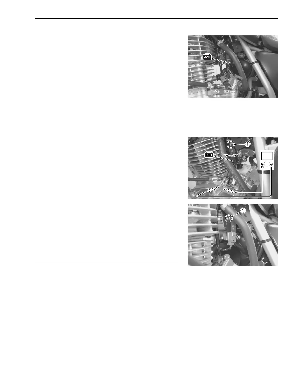
TPS ADJUSTMENT
Inspect the TP sensor setting position and adjust it if necessary
in the following procedures:
1) Connect the special tool between TP sensor and its coupler.
09900-28630: TP Sensor test lead
2) Warm up the engine and keep it running at idling speed.
3) Measure the TP sensor output voltage at the terminals.
(between + V and - B/Br)
NOTE:
When measure the TP sensor output voltage, make sure that
the fast idle cam is not contacted to the throttle lever.
09900-25008: Malti circuit tester set
Tester knob indication: Voltage ()
4) Loosen the TP sensor mounting screw 1 using the special
tool and turn the TP sensor to turning the specified value
(0.6 V).
09930-11950: Torx wrench (5 mm)
5) Tighten the TP sensor mounting screw 1 to the specified
torque.
TP sensor mounting screw:
3.5 N·m (0.35 kgf-m, 2.5 lb-ft)
09930-11950: Torx wrench (5 mm)
6) Turn off the engine and connect the TP sensor coupler.
V
After adjusted the TP sensor, perform the TP learned
value reset with special tool. (4-40)