FI SYSTEM DIAGNOSIS 4-49
“23” (P1651-H/L) TO SENSOR CIRCUIT MALFUNCTION
INSPECTION
NOTE:
After repairing the trouble, clear the DTC using SDS tool.
(4-24)
Step 1 (When indicating 23:)
1) Turn the ignition switch OFF.
2) Check the TO sensor coupler for loose or poor contacts.
If OK, then measure the TO sensor resistance.
3) Remove the TO sensor. (4-71)
DETECTED CONDITION POSSIBLE CAUSE
23 The sensor voltage is not within the fol-
lowing range.
0.2 V Sensor voltage < 4.8 V
• TO sensor circuit open or short
• TO sensor malfunction
• ECM malfunction
P1651
H
Sensor voltage is higher than specified
value.
• TO sensor circuit shorted to VCC or ground circuit
open
• TO sensor circuit open or shorted to ground or
VCC circuit open
L
Sensor voltage is lower than specified
value.
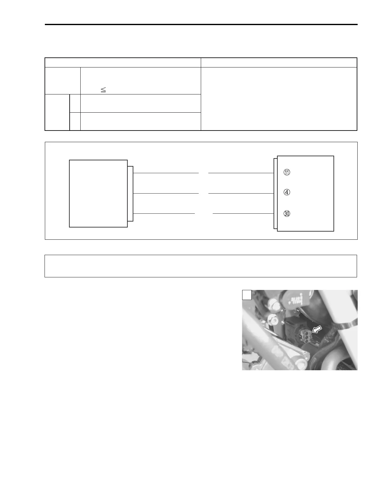
ECM
E2
TO
VCC
Br
R
B/Br
TO sensor
When using the multi circuit tester, do not strongly touch the terminal of the ECM coupler with
a needle-point probe to prevent the terminal damage or terminal bend.
1

 Loading...