Instrument Option$-455/A2/B2
CIRCUIT DESCRIPTION
BLOCK DIAGRAM SWITCHING
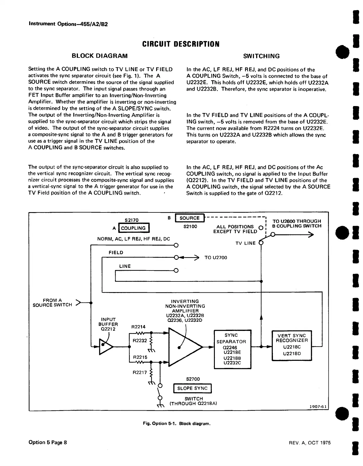
Setting the A COUPLING switch to TV LINE or TV FIELD
activates the sync separator circuit (see Fig. 1). The A
SOURCE switch determines the source of the signal supplied
to the sync separator. The input signal passes through an
FET Input Buffer amplifier to an Inverting/Non-Inverting
Amplifier. Whether the amplifier is inverting or non-inverting
is determined by the setting of the A SLOPE/SYNC switch.
The output of the Inverting/Non-Inverting Amplifier is
supplied to the sync-separator circuit which strips the signal
of video. The output of the sync-separator circuit supplies
a composite-sync signal to the A and B trigger generators for
use as a trigger signal in the TV LINE position of the
A COUPLING and B SOURCE switches.
The output of the sync-separator circuit is also supplied to
the vertical sync recognizer circuit. The vertical sync recog
nizer circuit processes the composite-sync signal and supplies
a vertical-sync signal to the A trigger generator for use in the
TV Field position of the A COUPLING switch.
In the AC, LF REJ, HF REJ, and DC positions of the
A COUPLING Switch, —5 volts is connected to the base of
U2232E. This holds off U2232E, which holds off U2232A
and U2232B. Therefore, the sync separator is inoperative.
In the TV FIELD and TV LINE positions of the A COUPL
ING switch, —5 volts is removed from the base of U2232E.
The current now available from R2224 turns on U2232E.
This turns on U2232A and U2232B which allows the sync
separator to operate.
In the AC, LF REJ, HF REJ, and DC positions of the Ac
COUPLING switch, no signal is applied to the Input Buffer
(Q2212). In the TV FIELD and TV LINE positions of the
A COUPLING switch, the signal selected by the A SOURCE
Switch is supplied to the gate of Q2212.
Fig. Option 5-1. Block diagram.
Option 5 Page 8
REV. A, OCT 1975

 Loading...


