Performance Check—455/A2/B2
d. Set generator frequency to 50 kHz (reference) and
adjust output amplitude for 5 division display.
e. Set generator frequency to 50 MHz.
f. CHECK—Display amplitude is at least 3.5 divisions.
10. X BANDWIDTH
a. Set: VERT MODE CH 2
ATIM E /D IV X-Y
INTENSITY for visible display
b. Set generator frequency to 50 kHz (reference) and
adjust output amplitude for 10 divisions of horizontal
deflection. Center trace horizontally with horizontal
POSITION control.
c. Set generator frequency to 3 MHz.
12. LOW FREQUENCY TRIGGERING
A TIME/DIV
10 ms
B TIME/DIV
10 ms
X I0 MAG out (off)
A and B COUPLING AC
A and B SOURCE NORM
VERT MODE
CH 1
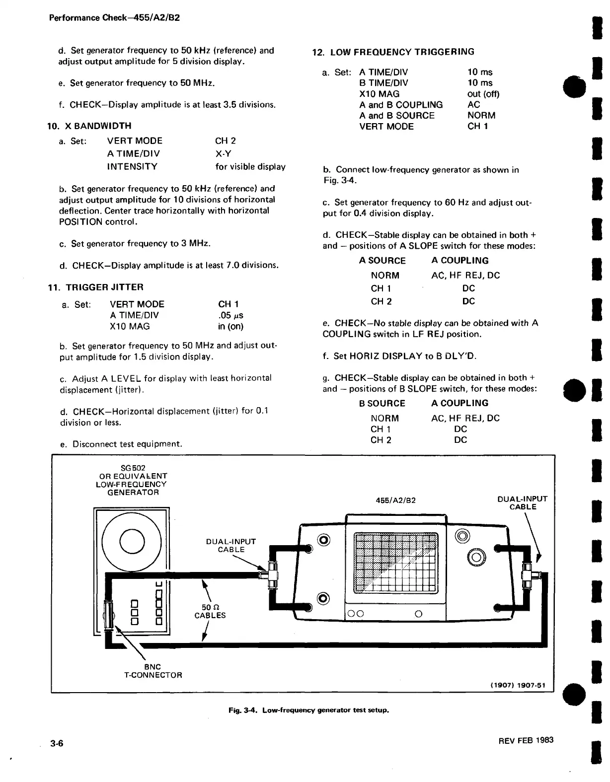
b. Connect low-frequency generator as shown in
Fig. 3-4.
c. Set generator frequency to 60 Hz and adjust out
put for 0.4 division display.
d. CHECK—Stable display can be obtained in both +
and — positions of A SLOPE switch for these modes:
d. CHECK—Display amplitude is at least 7.0 divisions.
11. TRIGGER JITTER
a. Set: VERT MODE CH 1
A TIME/DIV .05 juS
X I0 MAG in (on)
b. Set generator frequency to 50 MHz and adjust out
put amplitude for 1.5 division display.
A SOURCE A COUPLING
NORM AC, HFREJ, DC
CH 1 DC
CH 2 DC
e. CHECK—No stable display can be obtained with A
COUPLING switch in LF REJ position.
f. Set HORIZ DISPLAY to B DLY'D.
c. Adjust A LEVEL for display with least horizontal
displacement (jitter).
d. CHECK—Horizontal displacement (jitter) for 0.1
division or less.
e. Disconnect test equipment.
g. CHECK—Stable display can be obtained in both +
and — positions of B SLOPE switch, for these modes:
B SOURCE A COUPLING
NORM AC, HF REJ, DC
CH 1 DC
CH 2 DC
SG 502
OR EQUIVALENT
LOW-FREQUENCY
GENERATOR
455/A 2/B2 DUAL-INPUT
CABLE
BNC
T-CONNECTOR
(1907) 1907-51
3-6
REV FEB 1983
Fig. 3-4. Low-frequency generator test setup.

 Loading...


