Circuit Description—455/A2/B2
Diode CR358 protects the Sweep Gate Amplifier in the
event that greater than +5 volts is applied to the + GATE
OUT connector.
CRT CIRCUIT ^
The CRT circuit provides the voltage levels and control
circuits to operate the crt. The circuitry consists of the z
axis amplifier, high-voltage oscillator, high-voltage re
gulator, +95 volt low-voltage supply, high-voltage rectifier,
high-voltage multiplier, and the crt controls.
High-Voltage Oscillator
Transistors Q552, Q556 comprise a high-voltage (HV)
oscillator that produces drive for high-voltage transformer
T550. Transistor Q556 and inductor L554 store additional
energy from the +32 volt unregulated supply (at high power
line voltages) and supply that energy to the HV transformer.
In this way, the additional energy is used, not lost in heat.
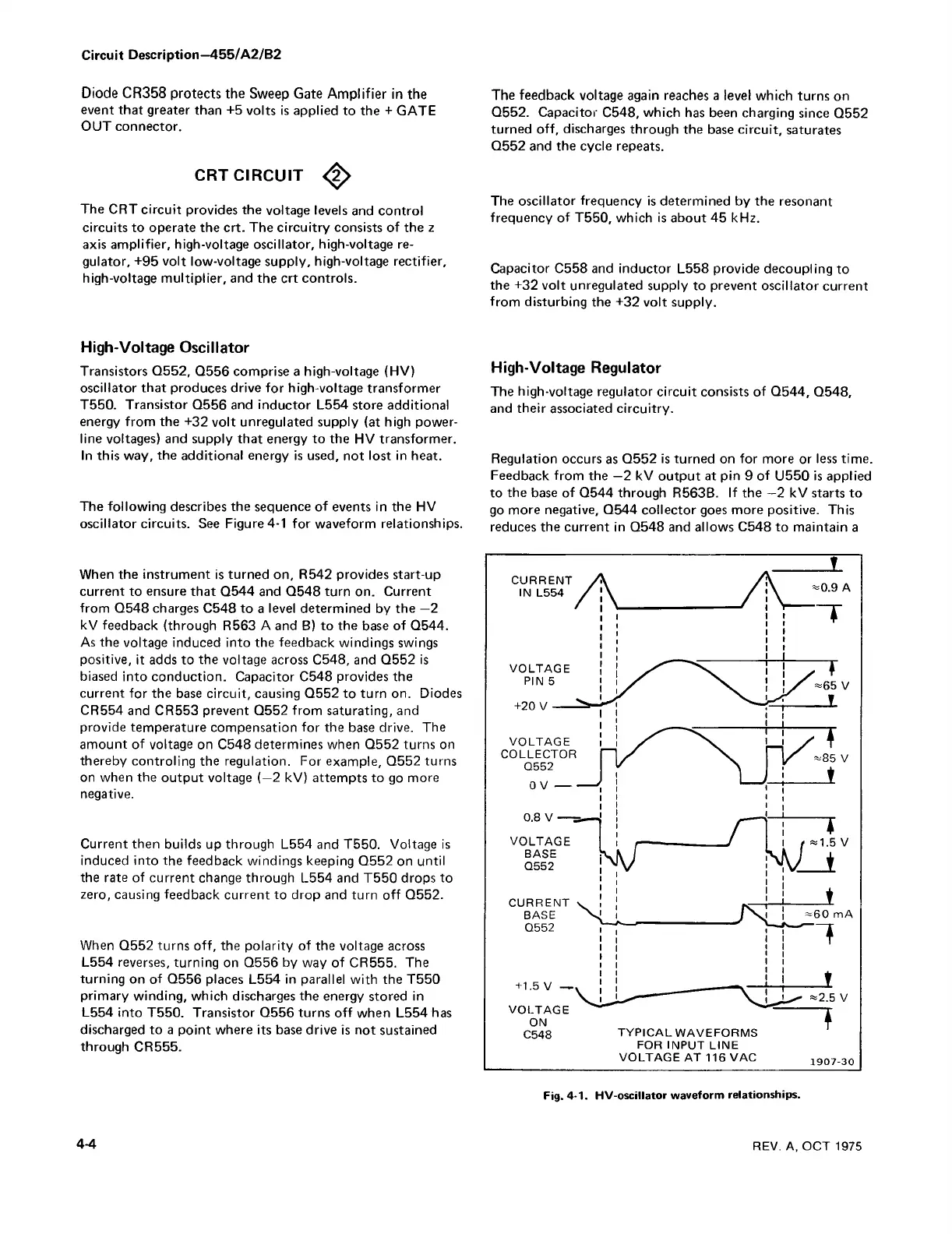
The following describes the sequence of events in the HV
oscillator circuits. See Figure 4-1 for waveform relationships.
When the instrument is turned on, R542 provides start-up
current to ensure that Q544 and Q548 turn on. Current
from Q548 charges C548 to a level determined by the —2
kV feedback (through R563 A and B) to the base of Q544.
As the voltage induced into the feedback windings swings
positive, it adds to the voltage across C548, and Q552 is
biased into conduction. Capacitor C548 provides the
current for the base circuit, causing Q552 to turn on. Diodes
CR554 and CR553 prevent Q552 from saturating, and
provide temperature compensation for the base drive. The
amount of voltage on C548 determines when Q552 turns on
thereby controling the regulation. For example, Q552 turns
on when the output voltage (—2 kV) attempts to go more
negative.
Current then builds up through L554 and T550. Voltage is
induced into the feedback windings keeping Q552 on until
the rate of current change through L554 and T550 drops to
zero, causing feedback current to drop and turn off Q552.
When Q552 turns off, the polarity of the voltage across
L554 reverses, turning on Q556 by way of CR555. The
turning on of Q556 places L554 in parallel with the T550
primary winding, which discharges the energy stored in
L554 into T550. Transistor Q556 turns off when L554 has
discharged to a point where its base drive is not sustained
through CR555.
The feedback voltage again reaches a level which turns on
Q552. Capacitor C548, which has been charging since Q552
turned off, discharges through the base circuit, saturates
Q552 and the cycle repeats.
The oscillator frequency is determined by the resonant
frequency of T550, which is about 45 kHz.
Capacitor C558 and inductor L558 provide decoupling to
the +32 volt unregulated supply to prevent oscillator current
from disturbing the +32 volt supply.
High-Voltage Regulator
The high-voltage regulator circuit consists of Q544, Q548,
and their associated circuitry.
Regulation occurs as Q552 is turned on for more or less time.
Feedback from the —2 kV output at pin 9 of U550 is applied
to the base of Q544 through R563B. If the —2 kV starts to
go more negative, Q544 collector goes more positive. This
reduces the current in Q548 and allows C548 to maintain a
Fig. 4-1. HV-oscillator waveform relationships.
4-4
REV. A, OCT 1975

 Loading...


