Operating Instructions—455/A2/B2
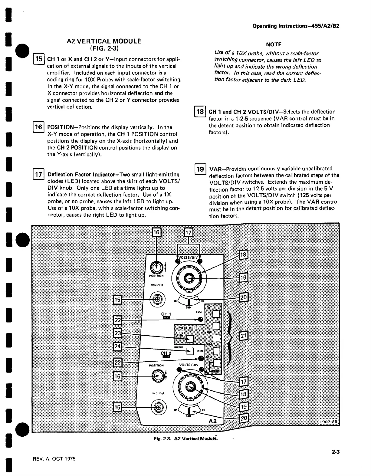
A2 V E R TICA L MODULE
(FIG . 2-3)
15
CH 1 or X and CH 2 or Y—Input connectors for appli
cation of external signals to the inputs of the vertical
amplifier. Included on each input connector is a
coding ring for 10X Probes with scale-factor switching.
In the X-Y mode, the signal connected to the CH 1 or
X connector provides horizontal deflection and the
signal connected to the CH 2 or Y connector provides
vertical deflection.
16 POSITION—Positions the display vertically. In the
X-Y mode of operation, the CH 1 POSITION control
positions the display on the X-axis (horizontally) and
the CH 2 POSITION control positions the display on
the Y-axis (vertically).
17
Deflection Factor Indicator—Two small light-emitting
diodes (LED) located above the skirt of each VOLTS/
DIV knob. Only one LED at a time lights up to
indicate the correct deflection factor. Use of a IX
probe, or no probe, causes the left LED to light up.
Use of a 10X probe, with a scale-factor switching con
nector, causes the right LED to light up.
NOTE
Use of a 10X probe, without a scale-factor
switching connector, causes the left LED to
light up and indicate the wrong deflection
factor, in this case, read the correct deflec
tion factor adjacent to the dark LED.
18
CH 1 and CH 2 VOLTS/DIV-Selects the deflection
factor in a 1-2-5 sequence (VAR control must be in
the detent position to obtain indicated deflection
factors).
19
VAR—Provides continuously variable uncalibrated
deflection factors between the calibrated steps of the
VOLTS/DIV switches. Extends the maximum de
flection factor to 12.5 volts per division in the 5 V
position of the VOLTS/DIV switch (125 volts per
division when using a 10X probe). The VAR control
must be in the detent position for calibrated deflec
tion factors.
Fig. 2-3. A2 Vertical Module.
REV. A, OCT 1975
2-3

 Loading...


