Adjustments—455/A2/B2
b. ADJUST—+32 V Adjust, R736, for +32 V. Refer to
Fig. 6-1.
A2. CRT BIAS
a. Set A TIME/DIV switch to X-Y.
b. Connect digital voltmeter between TP526 (see Fig.
6-2) and ground.
c. Set INTENSITY control for a +20 V reading.
d. Set FOCUS and ASTIG controls for well-defined spot.
If spot is not displayed, adjust Crt Bias adjustment, R532,
(see Fig. 6-3) for a visible spot. Then, adjust FOCUS and
ASTIG controls.
e. ADJUST—Crt Bias, R532, counterclockwise until
spot is just barely visible.
f. Disconnect digital voltmeter.
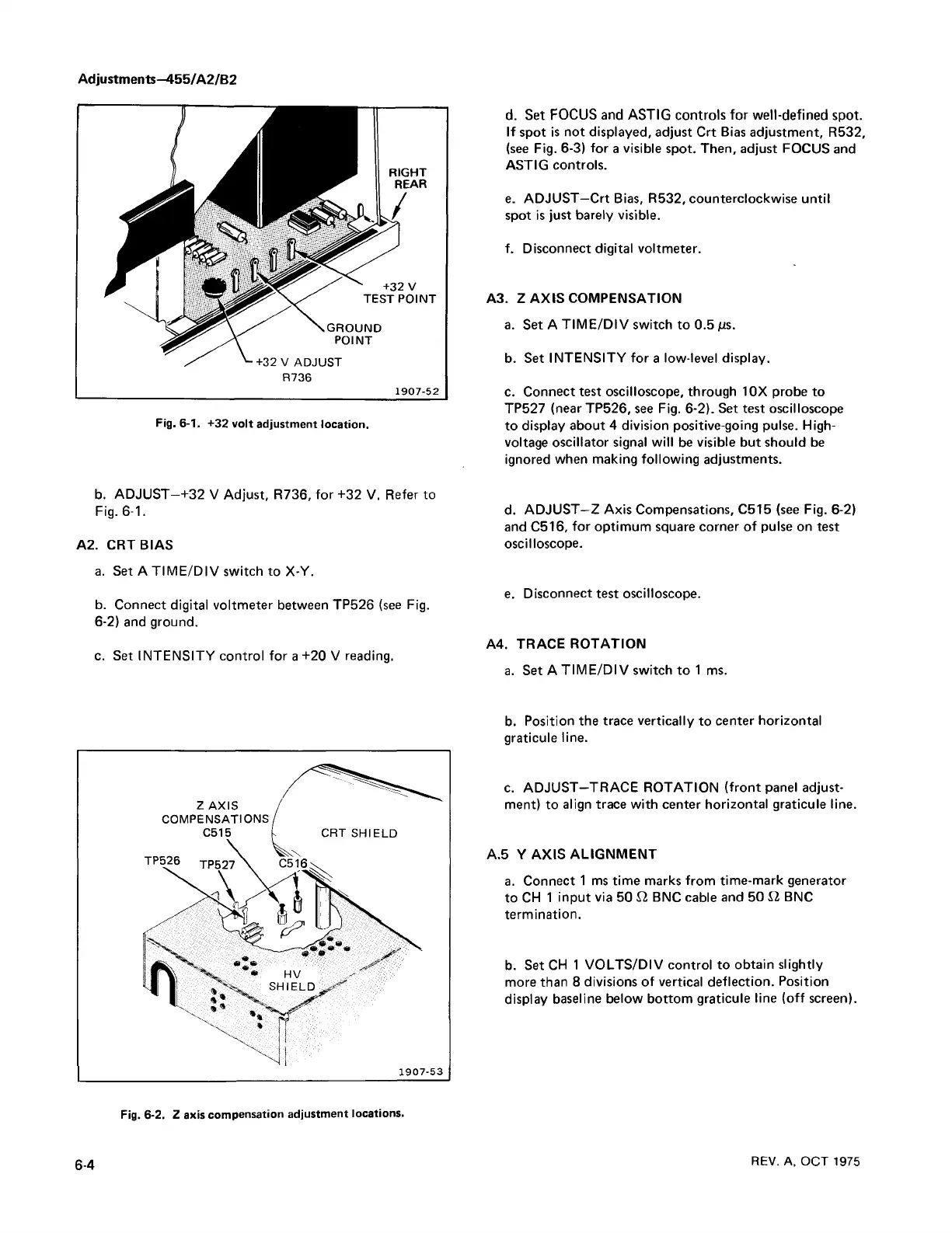
A3. Z AXIS COMPENSATION
a. Set A TIME/DIV switch to 0.5 /is.
b. Set INTENSITY for a low-level display.
c. Connect test oscilloscope, through 10X probe to
TP527 (near TP526, see Fig. 6-2). Set test oscilloscope
to display about 4 division positive-going pulse. High-
voltage oscillator signal will be visible but should be
ignored when making following adjustments.
d. ADJUST—Z Axis Compensations, C515 (see Fig. 6-2)
and C516, for optimum square corner of pulse on test
oscilloscope.
e. Disconnect test oscilloscope.
A4. TRACE ROTATION
a. Set A TIM E/DIV switch to 1 ms.
b. Position the trace vertically to center horizontal
graticule line.
c. ADJUST—TRACE ROTATION (front panel adjust
ment) to align trace with center horizontal graticule line.
A.5 Y AXIS ALIGNMENT
a. Connect 1 ms time marks from time-mark generator
to CH 1 input via 50 12 BNC cable and 50 12 BNC
termination.
b. Set CH 1 VOLTS/DIV control to obtain slightly
more than 8 divisions of vertical deflection. Position
display baseline below bottom graticule line (off screen).
6-4
REV. A, OC T 1975
Fig. 6-2. Z axis compensation adjustment locations.

 Loading...


