Circuit Description—455/A2/B2
Pin 13. Triggered light. Voltage at this pin lights the
TRIG light when a triggered gate has occurred.
Pin 14. Light ground. Provides a ground point for the
READY and TRIG lights.
Pin 15. Ready Light. Voltage at this pin lights the
READY light when the sweep is reset in the single sweep
mode.
Pin 16. +5 volt supply.
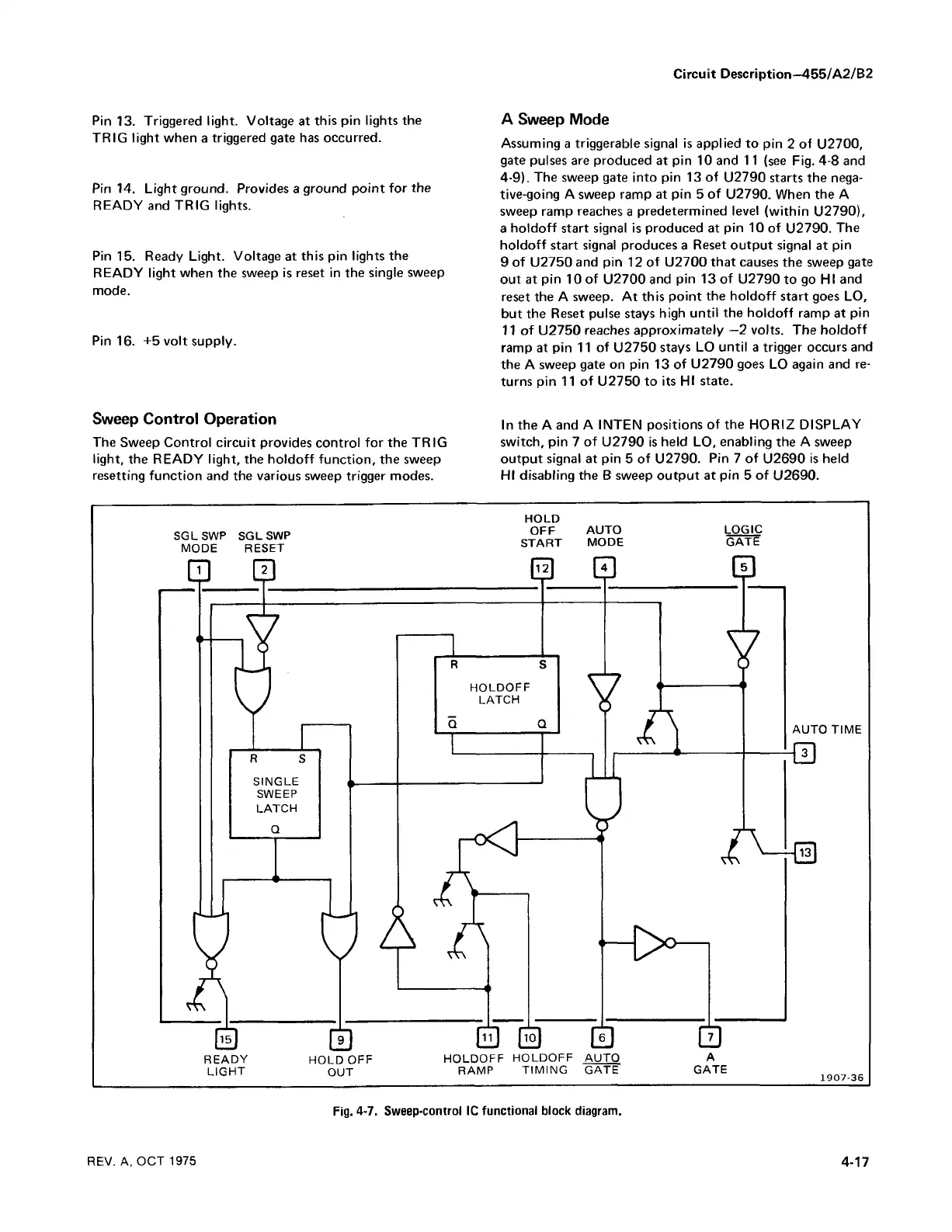
Sweep Control Operation
The Sweep Control circuit provides control for the TRIG
light, the READY light, the holdoff function, the sweep
resetting function and the various sweep trigger modes.
A Sweep Mode
Assuming a triggerable signal is applied to pin 2 of U2700,
gate pulses are produced at pin 10 and 11 (see Fig. 4-8 and
4-9). The sweep gate into pin 13 of U2790 starts the nega
tive-going A sweep ramp at pin 5 of U2790. When the A
sweep ramp reaches a predetermined level (within U2790),
a holdoff start signal is produced at pin 10 of U2790. The
holdoff start signal produces a Reset output signal at pin
9 of U2750 and pin 12 of U2700 that causes the sweep gate
out at pin 10 of U2700 and pin 13 of U2790 to go HI and
reset the A sweep. A t this point the holdoff start goes LO,
but the Reset pulse stays high until the holdoff ramp at pin
11 of U2750 reaches approximately —2 volts. The holdoff
ramp at pin 11 of U2750 stays LO until a trigger occurs and
the A sweep gate on pin 13 of U2790 goes LO again and re
turns pin 11 of U2750 to its HI state.
In the A and A INTEN positions of the HORIZ DISPLAY
switch, pin 7 of U2790 is held LO, enabling the A sweep
output signal at pin 5 of U2790. Pin 7 of U2690 is held
HI disabling the B sweep output at pin 5 of U2690.
SGLSWP SGLSWP
MODE RESET
HOLD
OFF AUTO LOGIC
START MODE GATE
LIGHT o u t r a m p t im in g g a t e g a t e
REV. A, OC T 1975
4-17
Fig. 4-7. Sweep-control 1C functional block diagram.

 Loading...


