Circuit Description—455/A2/B2
changing from one line voltage to the other, the line fuse
should be changed as follows: 1 amp fast blow for 116
volts or 0.5 amp fast blow for 232 volts.
The unused windings (pins 5, 6, 18, 19, 20, 21, and 22)
of T700 are provided for use with instrument options.
Secondary Circuit
Integrated circuits U722A, U722B and U762 are high-gain
amplifier cells with differential inputs. These amplifiers
monitor voltage variations in the output voltages and provide
correction signals to the series-regulating transistors.
Current limiting circuits provide short-circuit protection for
each of the regulated supplies. The following text discusses
the +32 volt current-limiting circuit. The other current-
limiting circuits operate similarly.
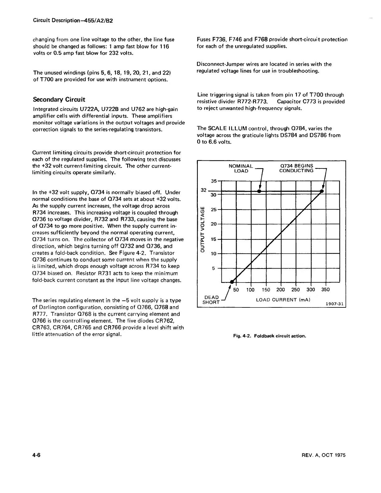
In the +32 volt supply, Q734 is normally biased off. Under
normal conditions the base of Q734 sets at about +32 volts.
As the supply current increases, the voltage drop across
R734 increases. This increasing voltage is coupled through
Q736 to voltage divider, R732 and R733, causing the base
of Q734 to go more positive. When the supply current in
creases sufficiently beyond the normal operating current,
Q734 turns on. The collector of Q734 moves in the negative
direction, which begins turning off Q732 and Q736, and
creates a fold-back condition. See Figure 4-2. Transistor
Q736 continues to conduct some current when the supply
is limited, which drops enough voltage across R734 to keep
Q734 biased on. Resistor R731 acts to keep the minimum
fold-back current constant as the input line voltage changes.
The series regulating element in the —5 volt supply is a type
of Darlington configuration, consisting of Q766, Q768 and
K i l l . Transistor Q768 is the current carrying element and
Q766 is the controlling element. The five diodes CR762,
CR763, CR764, CR765 and CR766 provide a level shift with
little attenuation of the error signal.
Fuses F736, F746 and F768 provide short-circuit protection
for each of the unregulated supplies.
Disconnect-Jumper wires are located in series with the
regulated voltage lines for use in troubleshooting.
Line triggering signal is taken from pin 17 of T700 through
resistive divider R772-R773. Capacitor C773 is provided
to reject unwanted high-frequency signals.
The SCALE ILLUM control, through Q784, varies the
voltage across the graticule lights DS784 and DS786 from
0 to 6.6 volts.
Fig. 4-2. Foldback circuit action.
4-6
REV. A, OCT 1975

 Loading...


