Adjustments—455/A2/B2
c. Set A TIME/DIV and VAR TIME/DIV controls to
obtain exactly one time mark/division (may be neces
sary to set A TIM E/DIV to .5 ms).
d. ADJUST-Y AXIS, R573 (see Fig. 6-3), to align
center time mark with center vertical graticule line.
e. INTERACTION—Position display baseline to center
horizontal graticule line and readjust TRACE ROTA
TION control. Then recheck Y Axis alignment.
A6. GEOMETRY
a. Adjust VAR timing and horizontal POSITION con
trols to align time markers with vertical graticule lines.
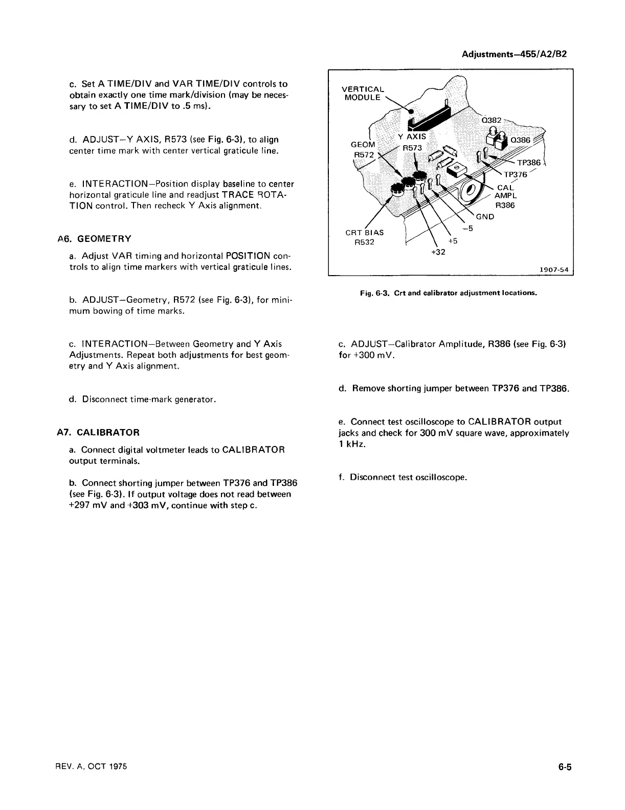
Fig. 6-3. Crt and calibrator adjustment locations.
b. ADJUST—Geometry, R572 (see Fig. 6-3), for mini
mum bowing of time marks.
c. INTERACTION—Between Geometry and Y Axis
Adjustments. Repeat both adjustments for best geom
etry and Y Axis alignment.
d. Disconnect time-mark generator.
A7. CALIBRATOR
a. Connect digital voltmeter leads to CALIBRATOR
output terminals.
b. Connect shorting jumper between TP376 and TP386
(see Fig. 6-3). If output voltage does not read between
+297 mV and +303 mV, continue with step c.
c. ADJUST—Calibrator Amplitude, R386 (see Fig. 6-3)
for +300 mV.
d. Remove shorting jumper between TP376 and TP386.
e. Connect test oscilloscope to CALIBRATOR output
jacks and check for 300 mV square wave, approximately
1 kHz.
f. Disconnect test oscilloscope.
REV. A, OCT 1975
6-5

 Loading...


