OPERATING INSTRUCTIONS
Section 2—455/A2/B2
OPERATING VOLTAGE
This instrument operates from either a 116 volt or 232 volt
nominal ac line-voltage source, 48 to 440 Hz. The line-
voltage selector switch at the rear of the instrument must
indicate the applied line voltage (116 V or 232 V).
The instrument can be damaged if operated on
232 volt nominal line-voltage source when the
line-voltage selector is set at 116 V.
To convert from one line voltage range to the other, move
the line-voltage selector switch, located on the rear of the
instrument, to indicate the correct nominal line voltage.
Change the fuse to the correct value; 1.0 amp, fast blow
for 116 volt operation and 0.5 amp, fast blow for 232 volt
operation.
SAFETY IN FORM ATIO N
This instrument is designed to operate from a single-phase
power source with one of the current-carrying conductors
(the neutral conductor) at ground (earth) potential. Opera
tion from power sources where both current-carrying con
ductor has over-current (fuse) protection within the
instrument.
This instrument has a 3-wire cord with a 3-terminal polar
ized plug for connection to the power source and safety-
earth. The ground terminal of the plug is directly connected
to the metal parts of the instrument. For electric-shock pro
tection, insert this plug in a mating outlet with a safety-earth
contact. If a 3-to-2 wire adapter is used to connect this in
strument to a 2-wire ac power system, be sure to connect
the ground lead of the adapter to earth (ground). Failure to
complete the ground system may allow the metal parts of
this instrument to be elevated above ground potential and
create a shock hazard.
Power Cord Conductor Identification
Conductor Color
Alternate Color
Ungrounded (Line) Brown
Black
Grounded (Neutral) Blue
White
Grounding (Earthing)
Green-Yellow
Green-Yellow
IN STRUMEN T COOLING
To maintain adequate instrument cooling, the ventilation
holes in the equipment cabinet must remain open, and the
air filter must be cleaned or replaced when it gets dirty.
FUNCTIONS OF CONTROLS, CONNECTORS AND INDICATORS
455 M A IN MODULE
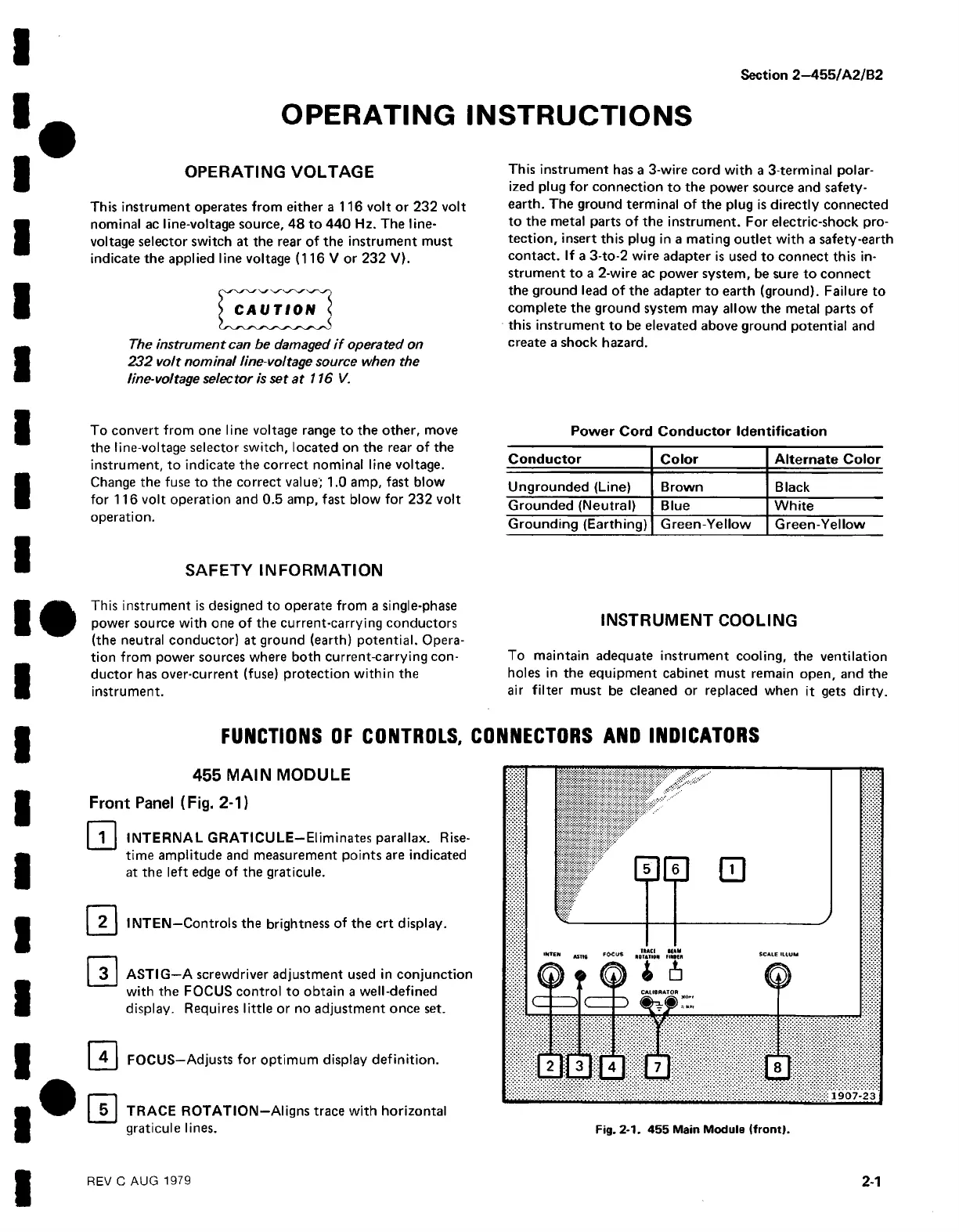
Front Panel (Fig. 2-1)
0 INTERNAL GRATICULE-EI iminates parallax. Rise
time amplitude and measurement points are indicated
at the left edge of the graticule.
INTEN—Controls the brightness of the crt display.
ASTIG—A screwdriver adjustment used in conjunction
with the FOCUS control to obtain a well-defined
display. Requires little or no adjustment once set.
0 FOCUS—Adjusts for optimum display definition.
| 5 | TRACE ROTATION—Aligns trace with horizontal
graticule lines.
REV C AUG 1979
2-1

 Loading...


