Maintenance—455/A2/B2
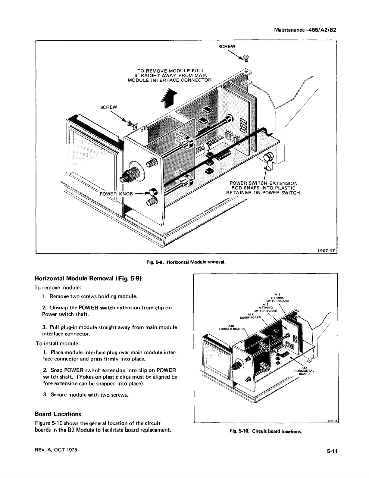
SCREW
TO REMOVE MODULE PULL
STRAIGHT AWAY FROM MAIN
MODULE INTERFACE CONNECTOR
POWER SWITCH EXTENSION
ROD SNAPS INTO PLASTIC
RETAINER ON POWER SWITCH
1907-47
Fig. 5-9. Horizontal Module removal.
Horizontal Module Removal (Fig. 5-9)
To remove module:
1. Remove two screws holding module.
2. Unsnap the POWER switch extension from clip on
Power switch shaft.
3. Pull plug-in module straight away from main module
interface connector.
To install module:
1. Place module interface plug over main module inter
face connector and press firm ly into place.
2. Snap POWER switch extension into clip on POWER
switch shaft. (Yokes on plastic clips must be aligned be
fore extension can be snapped into place).
3. Secure module with two screws.
Board Locations
Figure 5-10 shows the general location of the circuit
boards in the B2 Module to facilitate board replacement.
A14
B TIMING
SWITCH BOARD
1907-48
Fig. 5-10. Circuit board locations.
REV. A, OCT 1975
5-11

 Loading...


