Maintenance—455/A2/B2
2. Remove plastic bezel and filter from front of crt (held
with 4 screws).
3. Unplug crt anode lead and discharge to chassis.
4. Unplug crt base socket.
5. Disconnect 2 vertical deflection plate leads from left side
of crt neck.
6. Disconnect 2 horizontal deflection plate leads from
bottom of crt neck.
7. Hold crt face in one hand and slowly push crt base with
other hand.
8. Carefully pull crt out of shield.
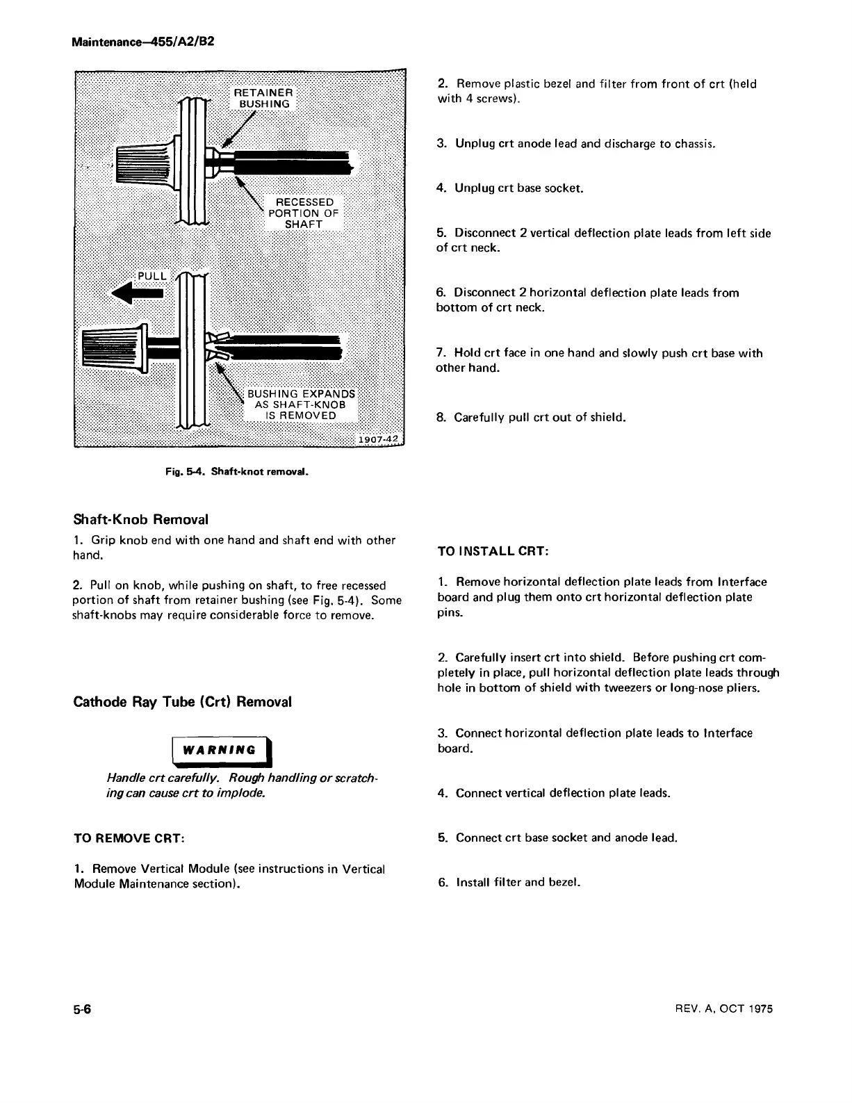
Fig. 5-4. Shaft-knot removal.
RETAINER:
BUSHING :
/
\
RECESSED
PORTION OF
SHAFT
BUSHING EXPANDS;
AS SHAFT-KNOB ;
IS REMOVED
: 1907-42 ;
Shaft-Knob Removal
1. Grip knob end with one hand and shaft end with other
hand.
2. Pull on knob, while pushing on shaft, to free recessed
portion of shaft from retainer bushing (see Fig. 5-4). Some
shaft-knobs may require considerable force to remove.
Cathode Ray Tube (Crt) Removal
WARNING
Handle crt carefully. Rough handling or scratch
ing can cause crt to implode.
TO REMOVE CRT:
1. Remove Vertical Module (see instructions in Vertical
Module Maintenance section).
TO INSTALL CRT:
1. Remove horizontal deflection plate leads from Interface
board and plug them onto crt horizontal deflection plate
pins.
2. Carefully insert crt into shield. Before pushing crt com
pletely in place, pull horizontal deflection plate leads through
hole in bottom of shield with tweezers or long-nose pliers.
3. Connect horizontal deflection plate leads to Interface
board.
4. Connect vertical deflection plate leads.
5. Connect crt base socket and anode lead.
6. Install filter and bezel.
5-6
REV. A, OCT 1975

 Loading...


