Instrument Options—455/A2/B2
ADJUSTMENT PROCEDURE
1. OPERATING RANGE
a. Connect the dc source to the oscilloscope equipped
with Option 7. Operate the oscilloscope in the 24 V mode.
Connect the voltmeter between fuse, F I601 (B) and the
common negative return (A). Vary the dc source from
28 V to 22 V.
CHECK—Oscilloscope should operate over the voltage
range.
a. Operate the oscilloscope in the 24 V mode.
b. Set the variable power supply output for 24 V.
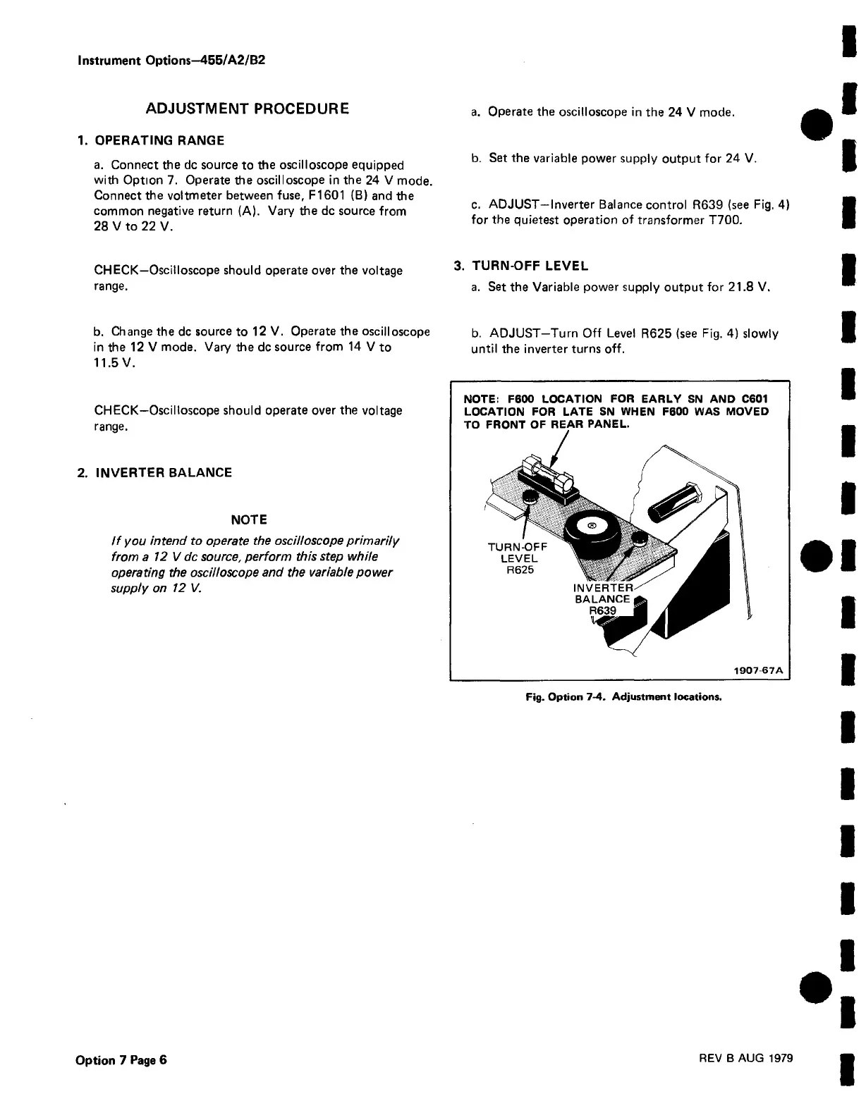
c. ADJUST—Inverter Balance control R639 (see Fig. 4)
for the quietest operation of transformer T700.
3. TURN-OFF LEVEL
a. Set the Variable power supply output for 21.8 V.
b. Change the dc source to 12 V. Operate the oscilloscope b. ADJUST-Turn Off Level R625 (see Fig. 4) slowly
in the 12 V mode. Vary the dc source from 14 V to until the inverter turns off.
11.5 V.
CHECK—Oscilloscope should operate over the voltage
range.
2. INVERTER BALANCE
NOTE
If you intend to operate the oscilloscope primarily
from a 12 V dc source, perform this step while
operating the oscilloscope and the variable power
supply on 12 V.
NOTE: F600 LOCATION FOR EARLY SN AND C601
LOCATION FOR LATE SN WHEN F600 WAS MOVED
TO FRONT OF REAR PANEL.
1907 67A
Fig. Option 7-4. Adjustment locations.
Option 7 Page 6
REV B AUG 1979

 Loading...


