Performance Check—455/A2/B2
4. TRIGGER VIEW GAIN
a. Set: VERT MODE CH 1
A SOURCE EXT ^ 1 0
ASLOPE OUT: +
ATIM E/D IV .2 ms
5. TRIGGER VIEW DELAY DIFFERENCE
a. Set: AT IM E/D IV ,05ms
X10 MAG
in (on)
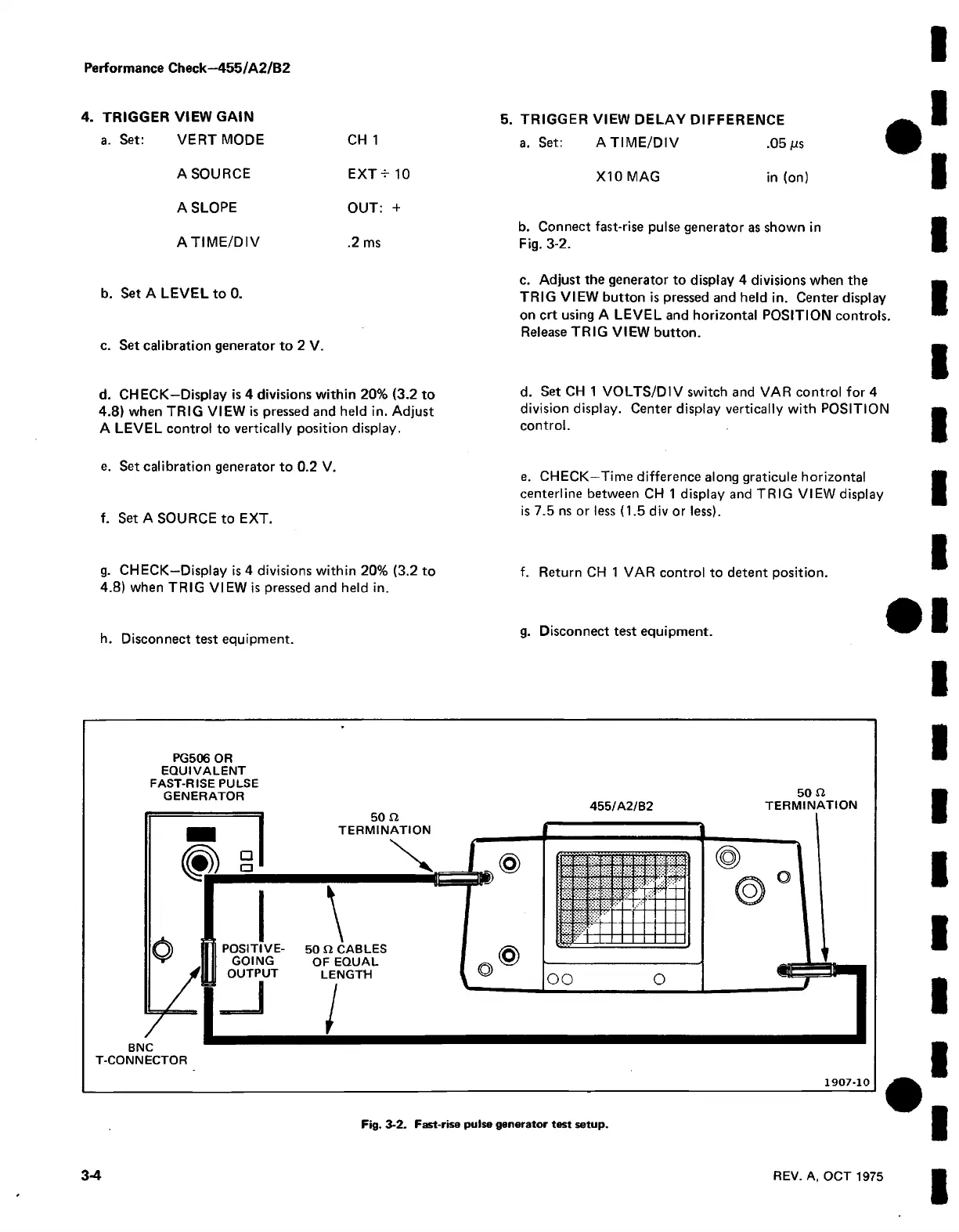
b. Connect fast-rise pulse generator as shown in
Fig. 3-2.
b. Set A LEVEL to 0.
c. Set calibration generator to 2 V.
c. Adjust the generator to display 4 divisions when the
TRIG VIEW button is pressed and held in. Center display
on crt using A LEVEL and horizontal POSITION controls.
Release TRIG VIEW button.
d. CHECK—Display is 4 divisions within 20% (3.2 to
4.8) when TRIG VIEW is pressed and held in. Adjust
A LEVEL control to vertically position display.
e. Set calibration generator to 0.2 V.
f. Set A SOURCE to EXT.
d. Set CH 1 VOLTS/DIV switch and VAR control for 4
division display. Center display vertically with POSITION
control.
e. CHECK—Time difference along graticule horizontal
centerline between CH 1 display and TRIG VIEW display
is 7.5 ns or less (1.5 div or less).
g. CHECK-Display is 4 divisions within 20% (3.2 to f. Return CH 1 VAR control to detent position.
4.8) when TRIG VIEW is pressed and held in.
h. Disconnect test equipment.
g. Disconnect test equipment.
PG506 OR
EQ UIVALENT
FAST-RISE PULSE
GENERATOR 50 a
455/A 2/B2 TERM INA TIO N
1907-10
Fig. 3-2. Fast-rise pulse generator test setup.
3-4
REV. A, OCT 1975

 Loading...


