Operating Instructions—455/A2/B2
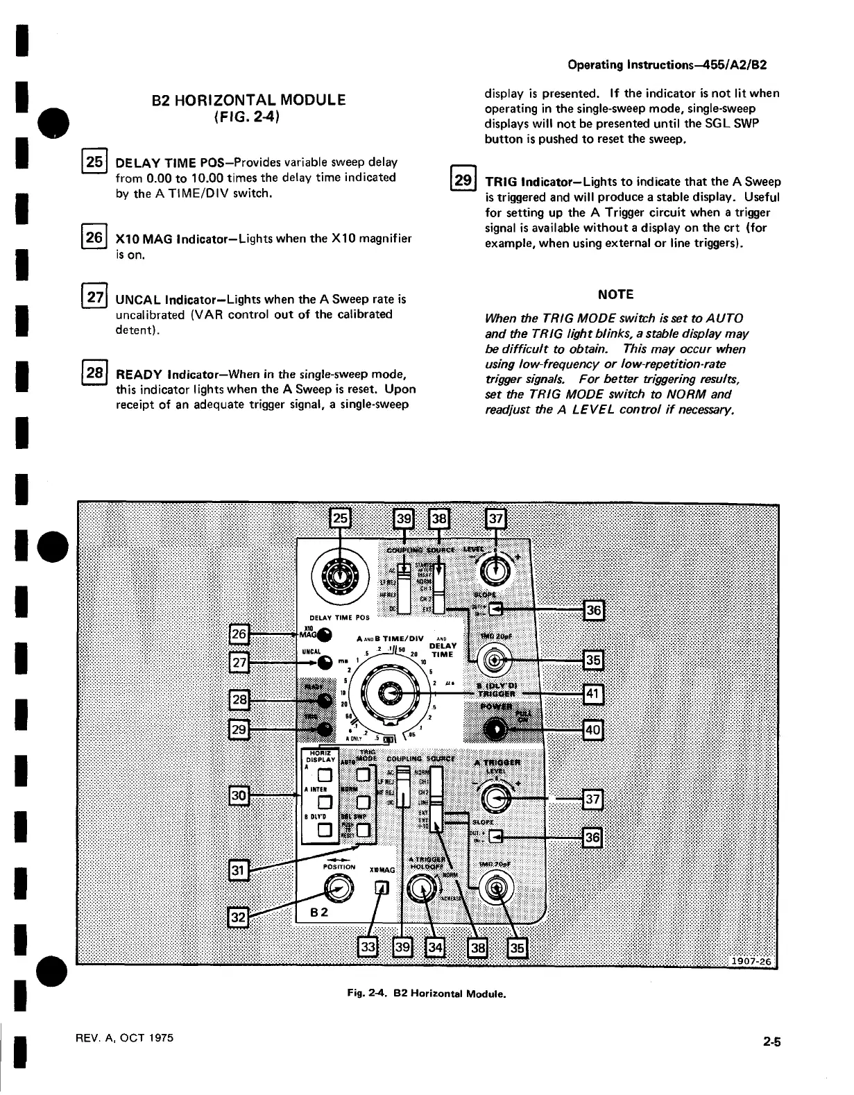
B2 H O R IZO NTAL MODULE
(FIG . 2-4)
25
DELAY TIME POS—Provides variable sweep delay
from 0.00 to 10.00 times the delay time indicated
by the A TIME/DIV switch.
26 X10 MAG Indicator—Lights when the X10 magnifier
is on.
display is presented. If the indicator is not lit when
operating in the single-sweep mode, single-sweep
displays will not be presented until the SGL SWP
button is pushed to reset the sweep.
29
TRIG Indicator—Lights to indicate that the A Sweep
is triggered and will produce a stable display. Useful
for setting up the A Trigger circuit when a trigger
signal is available without a display on the crt (for
example, when using external or line triggers).
27
UNCAL Indicator—Lights when the A Sweep rate is
uncalibrated (VAR control out of the calibrated
detent).
28 READY Indicator—When in the single-sweep mode,
this indicator lights when the A Sweep is reset. Upon
receipt of an adequate trigger signal, a single-sweep
NOTE
When the TRIG MODE switch is set to AUTO
and the TRIG light blinks, a stable display may
be difficult to obtain. This may occur when
using low-frequency or low-repetition-rate
trigger signals. For better triggering results,
set the TRIG MODE switch to NORM and
readjust the A LEVEL control i f necessary.
Fig. 2-4. B2 Horizontal Module.
REV. A, OCT 1975
2-5

 Loading...


