Instrument Options—455/A2/B2
VOLTAGE CONDITIONS
Voltages shown on this schematic diagram were measured with a Tektronix DM 501 Digital Multimeter. Voltage measurements can vary as
much as ±20%.
The B2 A COUPLING switch was set in the FIELD position.
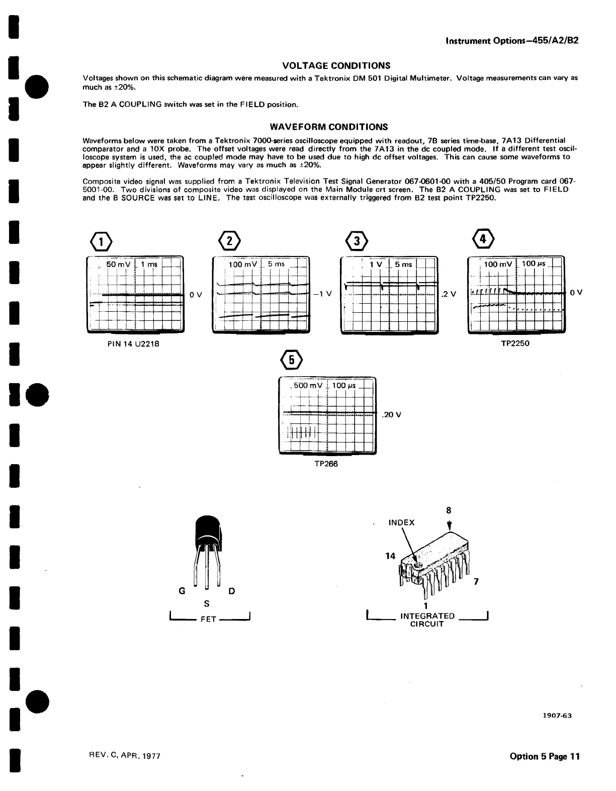
WAVEFORM CONDITIONS
Waveforms below were taken from a Tektronix 7000-series oscilloscope equipped with readout, 7B series time-base, 7A13 Differential
comparator and a 10X probe. The offset voltages were read directly from the 7A13 in the dc coupled mode. If a different test oscil
loscope system is used, the ac coupled mode may have to be used due to high dc offset voltages. This can cause some waveforms to
appear slightly different. Waveforms may vary as much as ±20%.
Composite video signal was supplied from a Tektronix Television Test Signal Generator 067-0601-00 with a 405/50 Program card 067-
5001-00. Two divisions of composite video was displayed on the Main Module crt screen. The B2 A COUPLING was set to FIELD
and the B SOURCE was set to LINE. The test oscilloscope was externally triggered from B2 test point TP2250.
(T) <2> <3> <i)
5 0
m
V
. 1
nr s
— —
i
00
m
V t 1
oo
j
i;X l l
LL
LG
_ i
|
i'"
* 'L -
, ,
,
,
* . i
j
!
- , L
100
m
V
!
5 rr
is
-
j
I
PIN 14 U2218 TP2250
0
.20 V
8
|
______
INTEGRATED |
CIRCUIT
1907-63
REV. C, APR. 1977
Option 5 Page 11

 Loading...


