Section 9-455/A2/B2
DIAGRAMS AND CIRCUIT BOARD ILLUSTRATIONS
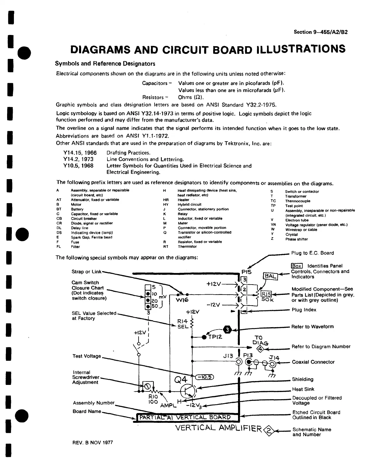
Symbols and Reference Designators
Electrical components shown on the diagrams are in the following units unless noted otherwise:
Capacitors = Values one or greater are in picofarads (pF).
Values less than one are in microfarads (pF).
Resistors = Ohms (£2).
Graphic symbols and class designation letters are based on ANSI Standard V32.2-1975.
Logic symbology is based on ANSI Y32.14-1973 in terms of positive logic. Logic symbols depict the logic
function performed and may differ from the manufacturer's data.
The overline on a signal name indicates that the signal performs its intended function when it goes to the low state.
Abbreviations are based on ANSI Y1.1-1972.
Other ANSI standards that are used in the preparation of diagrams by Tektronix, Inc. are:
Y14.15, 1966 Drafting Practices.
Y14.2, 1973 Line Conventions and Lettering.
Y10.5,1968 Letter Symbols for Quantities Used in Electrical Science and
Electrical Engineering.
The
following prefix letters are used as reference designators to identify components or assemblies on the diagrams.
A
Assembly, separable or repairable
H
Heat dissipating device (heat sink,
S
Switch or contactor
(circuit board, etc) heat radiator, etc)
T
T ransformer
AT
Attenuator, fixed or variable
HR
Heater
TC Thermocouple
B
Motor HY
Hybrid circuit
TP
Test point
BT
Battery J
Connector, stationary portion
U
Assembly, inseparable or non-repairable
C
Capacitor, fixed or variable K Relay
(integrated circuit, etc.)
CB
Circuit breaker
L
Inductor, fixed or variable
V
Electron tube
CR Diode, signal or rectifier M
Meter
VR
Voltage regulator (zener diode, etc.)
DL
Delay line
P
Connector, movable portion
W
Wirestrap or cable
DS Indicating device (lamp)
Q
Transistor or silicon-controlled
Y
Crystal
E
Spark Gap, Ferrite bead
rectifier
2
Phase shifter
F
Fuse
R
Resistor, fixed or variable
FL
Filter
RT
Thermistor
,— Plug to E.C. Board
The following special symbols may appear on the diagrams: S
Strap or Link
Cam Switch
Closure Chart
(Dot indicates
switch closure)
SEL Value Selected
at Factory
Test Voltage
Internal
Screwdriver
Adjustment
Assembly Number
Board Name
VERTICAL A M P L IF IE R ^**.
I Box I Identifies Panel
Controls, Connectors and
Indicators
___ Modified Component—See
Ini s] < Parts List (Depicted in grey,
5 0 k or with grey outline)
Plug Index
Refer to Waveform
Refer to Diagram Number
Coaxial Connector
Shielding
Heat Sink
Decoupled or Filtered
Voltage
Etched Circuit Board
Outlined in Black
Schematic Name
and Number
REV. B NOV 1977

 Loading...


