Performance Check—455/A2/B2
6. CASCADED SENSITIVITY
VERT MODE
CH 2
CH 1 and CH 2 VOLTS/
DIV
5 mV
CH 1 and CH 2 AC-GND-
DC
DC
ATIM E/D IV
.2 ms
X10 MAG
out (off)
A SOURCE
NORM
b. Set generator frequency to 20 MHz.
c. CHECK—Display amplitude is at least 3.5 divisions.
8. CH 2 BANDWIDTH
a. Set VERT MODE to CH 2.
b. Set generator frequency to 50 kHz (reference) and
adjust output amplitude for 5 division display.
c. Set the generator frequency to 50 MHz.
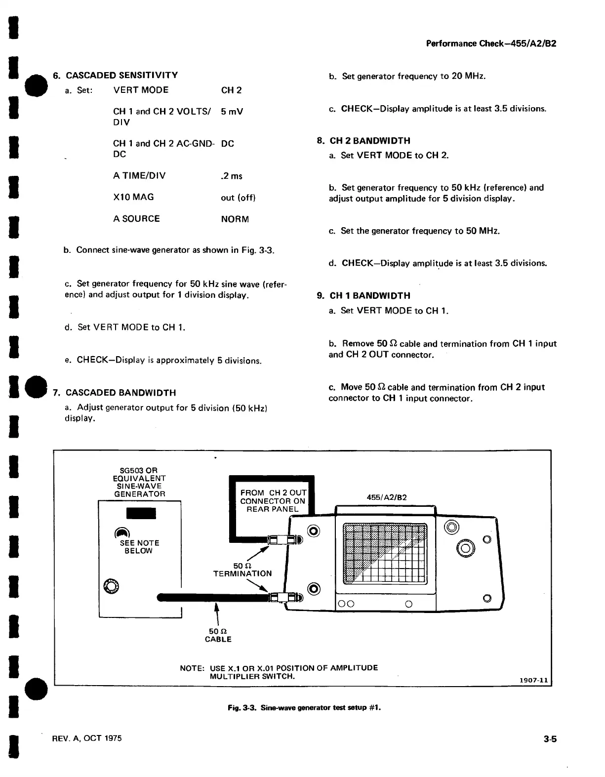
b. Connect sine-wave generator as shown in Fig. 3-3.
c. Set generator frequency for 50 kHz sine wave (refer
ence) and adjust output for 1 division display.
d. Set VERT MODE to CH 1.
e. CHECK—Display is approximately 5 divisions.
7. CASCADED BANDWIDTH
a. Adjust generator output for 5 division (50 kHz)
display.
d. CHECK—Display amplitude is at least 3.5 divisions.
9. CH 1 BANDWIDTH
a. Set VERT MODE to CH 1.
b. Remove 50 £2 cable and termination from CH 1 input
and CH 2 OUT connector.
c. Move 50 £2 cable and termination from CH 2 input
connector to CH 1 input connector.
SG503 OR
EQUIVALENT
SINE-WAVE
GENERATOR
(Rl
SEE NOTE
BELOW
' t
455/A2/B2
oo
o
50 fi
CABLE
NOTE: USE X.1 OR X.01 POSITION OF AMPLITUDE
MULTIPLIER SWITCH.
1907-11
Fig. 3-3. Sine-wave generator test setup #1.
REV. A, OCT 1975
3-5

 Loading...


